Engine oil control body

A control body and engine oil technology, applied in mechanical equipment, engine components, machines/engines, etc., can solve problems such as increased failure rate, difficult installation and maintenance, messy pipelines, etc., to simplify the lubrication system, facilitate maintenance, and beautify The effect of appearance

Active Publication Date: 2013-11-20
WEICHAI POWER CO LTD
View PDF5 Cites 4 Cited by
  • Summary
  • Abstract
  • Description
  • Claims
  • Application Information

AI Technical Summary

Problems solved by technology

[0009] 1. The lubricating oil circuit needs to arrange pipelines between the oil pump, oil filter, oil cooler, and the main oil passage of the body. The pipelines are too messy, easy to entangle, difficult to install and maintain, and also affect the overall engine beautiful
[0010] 2. At present, most engines use the method of installing a pressure limiting v...

Method used


Image

  • Engine oil control body
  • Engine oil control body
  • Engine oil control body

Examples


Embodiment Construction

[0039] In order to make those skilled in the art better understand the technical solutions of the present invention, the present invention will be further described in detail below with reference to the accompanying drawings and specific embodiments.

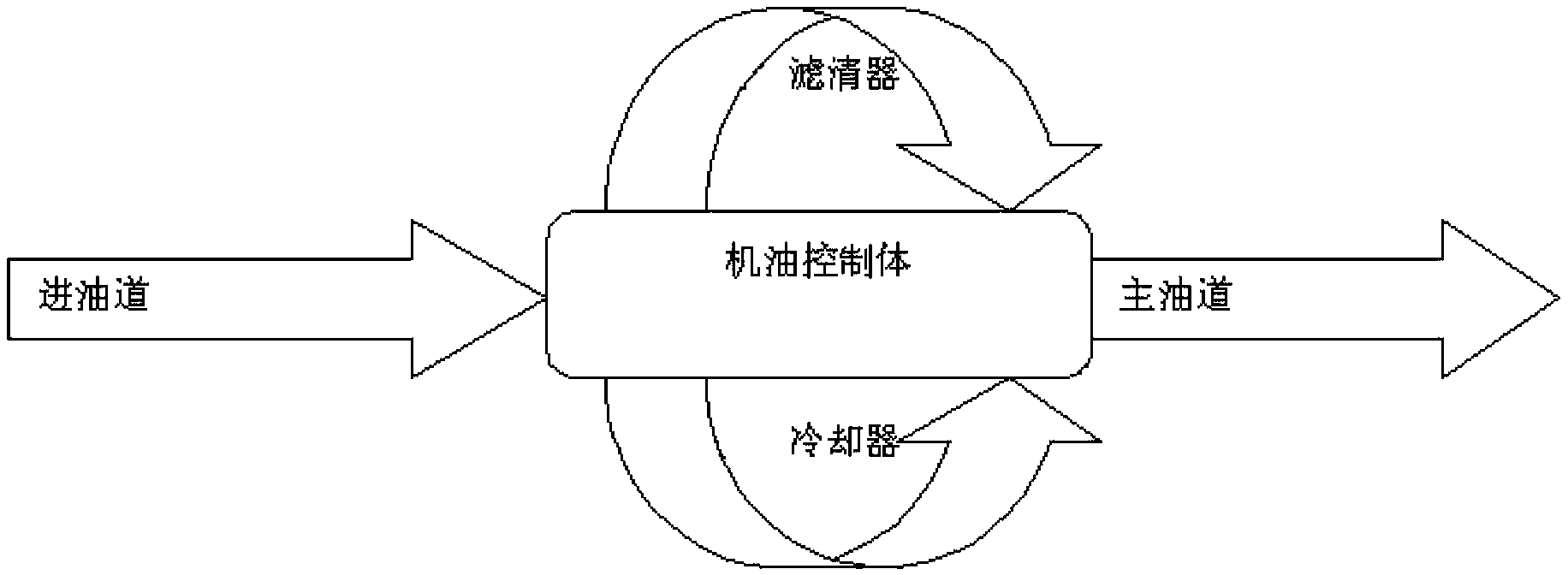
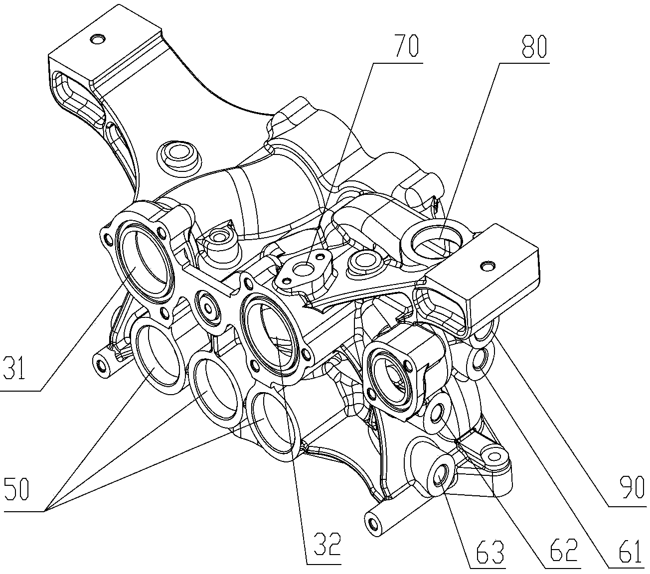
[0040] Please refer to Figure 2-7 , figure 2 A schematic diagram of the arrangement of the oil control body provided by the present invention; image 3 It is an axonometric view of a specific embodiment of the oil control body provided by the present invention; Figure 4 for lubricating oil image 3 Schematic diagram of the path when the oil control body is in the middle; Figure 5 for image 3 's main view; Image 6 for Figure 5 the rear view; Figure 7 for Figure 5 bottom view.

[0041] The oil control body has:

[0042] filter oil inlet port 31, filter oil outlet port 32, cooler oil inlet port 21, cooler oil outlet port 22, main oil passage oil inlet port 40, and oil pump oil outlet port 10;

[0043] They are a...


PUM


Abstract

The invention discloses an engine oil control body. The engine oil control body comprises a filter oil inlet connector, a filter oil outlet connector, a cooler oil inlet connector, a cooler oil outlet connector, a main oil channel oil inlet connector, an engine oil pump oil outlet connector, a first lubricating oil channel, a second lubricating oil channel and a third lubricating oil channel, wherein the first lubricating oil channel, the second lubricating oil channel and the third lubricating oil channel are arranged inside the engine oil control body, the first lubricating oil channel is communicated with the engine oil pump oil outlet connector and the cooler oil inlet connector, the second lubricating oil channel is communicated with the cooler oil outlet connector and the filter oil inlet connector, and the third lubricating oil channel is communicated with the filter oil outlet connector and the main oil channel oil inlet connector. An engine oil pump, a filter, a cooler and an engine main oil channel can be directly installed to the engine oil control body in a butt joint mode, a pipeline does not need to be arranged, the structure of a whole lubricating system is simplified, and appearance is beautified. The lubricating oil channels are arranged inside the engine oil control body to form an integral module and are not mutually interfered, and the state is stable. In addition, the engine oil control body serves as a supporting mechanism of the cooler and the filter, and the structure for supporting the cooler and the filter does not need to be specially arranged.

Description

technical field [0001] The invention relates to the technical field of engine lubrication systems, in particular to an oil control body. Background technique [0002] The lubricating system of the engine usually includes the oil pan, oil pump, oil cooler, oil filter, and parts of the body (with main oil passages, auxiliary oil passages, etc.) Keep the engine running normally. [0003] The oil filter is a device that filters the engine lubricating oil to keep the lubricating oil entering the engine body clean. [0004] The oil cooler is a device that cools the engine lubricating oil, realizes the cooling of the oil in the engine, ensures the pressure of the oil during operation and improves the service life of the oil. [0005] The main oil passage of the body is the main lubricating oil passage of the engine body, which mainly provides lubricating oil to the important parts such as the crankshaft, connecting rod and supercharger. [0006] Please refer to figure 1 underst...

Claims


Application Information

Patent Timeline
IPC IPC(8): F01M1/10F01M1/00
Inventor 王宝军朱杨侯斌唐金池
Owner WEICHAI POWER CO LTD
Why Eureka
Try Eureka