Clamping device used for measurement of thin plates

A clamping device, thin plate technology, applied in the direction of measuring devices, instruments, etc., can solve the problems of increased manufacturing cost, inability to absorb, air leakage, etc., and achieve the effect of avoiding damage

Inactive Publication Date: 2013-11-20
KUNSHAN YUNCO PRECISION IND TECH
View PDF6 Cites 3 Cited by
  • Summary
  • Abstract
  • Description
  • Claims
  • Application Information

AI Technical Summary

Problems solved by technology

This method uses vacuum adsorption to clamp the thin plate. Once the surface of the thin plate has microscopic deformation or unevenness, it will cause air leakage because the thin plate cannot be completely attached to the vacuum adsorption platform during the adsorption process. Good adsorption and firm
Once the fixation is not firm, it will have a great impact on the measurement accuracy and measurement benchmark
As the size of the thin plate becomes larger, the area of ​​the vacuum adsorption platform is required to increase, and the flatness requirement cannot be reduced, which will inevitably lead to an increase in the difficulty and cost of the vacuum adsorption platform itself.
In addition, once there are hollow features in the thin plate, it will not be able to be adsorbed on the vacuum adsorption platform

Method used


Image

  • Clamping device used for measurement of thin plates
  • Clamping device used for measurement of thin plates
  • Clamping device used for measurement of thin plates

Examples


Embodiment Construction

[0017] Embodiments of the present invention are described in detail below, examples of which are shown in the drawings, wherein the same or similar reference numerals designate the same or similar elements or elements having the same or similar functions throughout. The embodiments described below by referring to the figures are exemplary only for explaining the present invention and should not be construed as limiting the present invention.

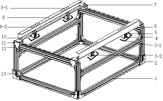
[0018] see figure 1 As shown, a clamping device for thin plate shape measurement includes an aluminum alloy profile frame 1, a profile frame fixing part 2, a cylinder fixing seat 3-2, an air inlet joint 4 under the cylinder, an air intake joint 5 on the cylinder, and a guide rail 6. Limiting block 7, pressure block 8, front and rear limit pins, sliding rod 10, sliding block 11, fixing plate 12 and profile frame corner connector 13, the main body of the clamping device is composed of aluminum alloy profile frame 1 through profile f...


PUM


Abstract

A clamping device used for measurement of thin plates comprises a device main body; the device main body comprises a proximate matter frame, a proximate matter frame fixing piece, a proximate matter frame corner connector, a guide rail, two slide blocks, pressing blocks, air cylinders and slide rods; the proximate matter frame takes the shape of a cuboid formed by connecting a plurality of pieces of proximate matter; the guide rail is fixed on the proximate matter in the front-back direction; the two slide blocks are arranged on the guide rail; the pressing blocks are fixed on the two slide blocks which are homodromous front and back; the air cylinders are mounted on the pressing blocks through air cylinder fixing seats at the bottoms of the pressing blocks, and two air cylinders are distributed on the same pressing block in the front-back direction; the slide rods are mounted on the inner surfaces of the pressing blocks. According to the invention, a thin plate is unfolded in a suspended and smooth manner without large-area contact type support, and then damage to the surface of the thin plate, caused by large-area contact type support, can be avoided to the greatest extent, so that professional clamping technology foundations are provided for improving the measurement of flatness, thickness and other shape features of the thin plate.

Description

technical field [0001] The invention relates to a measuring device, in particular to a clamping device for thin plate shape measurement. Background technique [0002] In the fields of surface mount technology (SMT), precision thin board manufacturing, etc., precision thin boards are manufactured or used in large quantities. For example, the stencil base material used in the surface mount industry, the material types involve stainless steel, nickel, nickel alloy, etc., the thickness is generally within 1mm, and in the process of its processing, it needs to go through electroforming, electroplating, polishing, etching, laser cutting And other processes, semi-finished products and final finished products in the middle need to be measured for thickness uniformity to ensure that the final product meets customer requirements; in terms of precision thin plate manufacturing, such as various stainless steels provided by large steel mills for the surface mount industry, etc. The pla...

Claims


Application Information

Patent Timeline
IPC IPC(8): G01B21/20
Inventor 夏发平
Owner KUNSHAN YUNCO PRECISION IND TECH
Why Eureka
Try Eureka