A Test Circuit for Residual Current Protection

A technology of protection test and residual current, applied in the field of circuit, can solve the problems of burning resistance, failure of test circuit function, and easy heating of resistance.

Active Publication Date: 2015-12-02
DELIXI ELECTRIC
View PDF7 Cites 0 Cited by
  • Summary
  • Abstract
  • Description
  • Claims
  • Application Information

AI Technical Summary

Problems solved by technology

In this design, if any one phase of L1 and L2 is missing, the function of the test circuit will fail. Both resistors R1 and R2 use resistors of tens of kiloohms and 1 watt. Pressing the test button for a long time will easily heat up the resistors, which may cause the resistors to be burned. The power supply of the test circuit is connected to the three-phase power supply, and the power supply voltage is high. When designing the circuit board, it is necessary to fully consider the problem of electrical clearance.

Method used


Image

  • A Test Circuit for Residual Current Protection
  • A Test Circuit for Residual Current Protection

Examples


Embodiment Construction

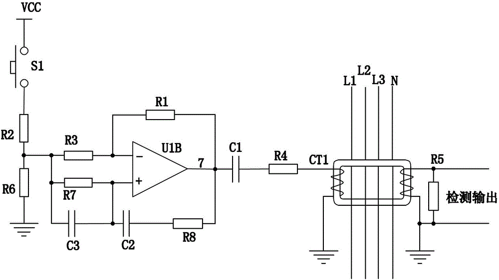
[0013] like figure 2 As shown, a residual current protection test circuit includes a test button S1, an operational amplifier U1, a Wien bridge circuit, an output circuit and a current transformer CT, wherein one end of the test button S1 is connected to an electrical signal, and the other end is passed through a resistor R2 and R6 are then grounded, and resistors R2 and R6 form a bias circuit to provide a bias voltage for the sine wave oscillator circuit. A signal is output by connecting the bias resistor R3 between the resistors R2 and R6, and the other end of the bias resistor R3 is connected to the inverting input terminal of the operational amplifier U1. The Wien bridge circuit includes a resistor R7, a resistor R8, Capacitor C2 and capacitor C3, wherein resistor R7 is connected in parallel with capacitor C3, and the front ends of resistor R7 and capacitor C3 are connected to the divided output voltage of resistor R2 and bias resistor R6. After resistor R7 is connected i...


PUM


Abstract

The invention relates to a circuit, in particular to a residual current protection testing circuit in a device with residual current protection. The residual current protection testing circuit is characterized in that the residual current protection testing circuit comprises a testing button S1, an operational amplifier U1, a Wien bridge circuit, an output circuit and a current transformer CT, and the Wien bridge circuit comprises a resistor R7, a resistor R8, a capacitor C2 and a capacitor C3. By adopting the scheme, the novel residual current protection testing circuit provided by the invention has the advantages that the problems existing in the prior art are overcome; since a sine wave oscillating circuit is used for simulating output current leakage testing signals, the circuit reliability is high and the circuit is not influenced by open phase and under-voltage of a three-phase power supply; and since a low-voltage power supply is used for supplying power, the power consumption is low, and the problems that heat is produced and power resistors are apt to damage due to a reason that a high-power resistor is used for decreasing voltage are avoided.

Description

technical field [0001] The invention relates to a circuit, especially a test circuit with residual current protection in a residual current protection device. Background technique [0002] Devices with residual current protection generally need to have a test circuit. Users can know whether the residual current protection function of the device is normal through the test circuit, which is of great significance to prevent electric shock and personal injury. [0003] At present, the test circuit with residual current protection takes power from two or three phases of the three-phase power supply, and is connected to the test coil of the residual current transformer through the form of a resistance step-down series connection test button. like figure 1 shown. In this design, if any one phase of L1 and L2 is missing, the function of the test circuit will fail. Both resistors R1 and R2 use resistors of tens of kiloohms and 1 watt. Pressing the test button for a long time will e...

Claims


Application Information

Patent Timeline
Patent Type & Authority Patents(China)
IPC IPC(8): G01R31/00
Inventor 李建模
Owner DELIXI ELECTRIC
Why Eureka
Try Eureka