Amplitude and phase calibration method for radio frequency channels of digital array secondary radar and antenna arrays

A technology of antenna elements and radio frequency channels, which is applied in the field of secondary radar, can solve problems such as the need to improve the accuracy, and achieve the effect of simple implementation, high calibration accuracy, fast and accurate calibration

Active Publication Date: 2013-11-20
四川九洲空管科技有限责任公司
View PDF2 Cites 20 Cited by
  • Summary
  • Abstract
  • Description
  • Claims
  • Application Information

AI Technical Summary

Problems solved by technology

The mid-field calibration method requires the antenna to have a high-frequency switch for gating the channe...

Method used


Image

  • Amplitude and phase calibration method for radio frequency channels of digital array secondary radar and antenna arrays
  • Amplitude and phase calibration method for radio frequency channels of digital array secondary radar and antenna arrays
  • Amplitude and phase calibration method for radio frequency channels of digital array secondary radar and antenna arrays

Examples


Embodiment 1

[0026] The first embodiment is emission calibration.

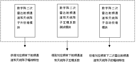
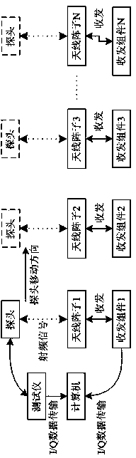
[0027] The external probe is used to scan in the direction facing the antenna element (moving from left to right or other ways) in sequence. The external probe is connected to the tester. When the probe is facing each antenna element, the tester sends out synchronization pulses to control the probe The transceiving component connected to the opposite antenna element transmits, and the tester converts the received signal into baseband I / Q data and transmits it to the computer for storage. Each antenna element connected to the transceiver component is tested separately to obtain the corresponding amplitude and phase value of each radio frequency channel and antenna element. Such as figure 2 The implementation schematic diagram of the external calibration module between the digital array secondary radar radio frequency channel and the antenna array is shown. When the probe moves to face the antenna element 1, the transceiver c...

Embodiment 2

[0031] The second embodiment is receiving calibration.

[0032] Triggered by the sync pulse, the tester transmits and the transceiver component converts the received signal into baseband I / Q data and transmits it to the computer for storage. According to the above-mentioned stored baseband I / Q data, the receiving amplitude and phase characteristics of each digital array secondary radar radio frequency channel and antenna element can be obtained.

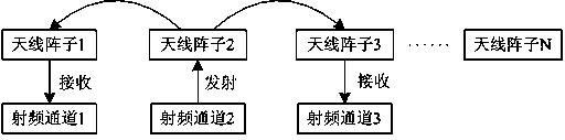
[0033] image 3 It is a schematic diagram of the realization of the receiving amplitude-phase relationship between the odd-numbered radio frequency channel and the antenna element. If the number of RF channels and antenna elements of the digital array secondary radar is N, then the RF channel and antenna elements 2K transmit, and the RF channel and antenna elements 2K-1 and 2K+1 receive at the same time, where 0


PUM


Abstract

The invention relates to the technical field of secondary radar, and discloses an amplitude and phase calibration method for radio frequency channels of digital array secondary radar and an antenna arrays. Different radio frequency channels of the digital array secondary radar and the antenna arrays carry out transmission and receiving at corresponding frequencies, and a relative amplitude and phase relationship between transmission beams and receiving beams of all radio frequency channels and the antenna arrays is determined under the condition that the different frequency channels of the digital array secondary radar and the antenna arrays carry out transmission and receiving at the corresponding frequencies; transmitting and receiving amplitude and phase characteristics of all radio frequency channels of the digital array secondary radar and the antenna arrays at the corresponding frequencies are calibrated according to a cross coupling relationship of the corresponding frequencies among the antenna arrays and by combining with the relative amplitude and phase relationship between the transmission beams and the receiving beams of all radio frequency channels of the digital array secondary radar and the antenna arrays at the corresponding frequencies.

Description

Technical field [0001] The invention relates to the technical field of secondary radars, in particular to a method for amplitude and phase calibration of digital array secondary radar radio frequency channels and antenna elements. Background technique [0002] The digital array secondary radar system adopts the design of distributed transceiver components and multi-channel antenna array transceivers. Since the distributed transceiver components are active RF channels, the amplitude and phase characteristics of the RF channels will change over time. This leads to changes in the shape of the transmitting and receiving beams of the secondary radar system, which affects the performance of the system. At this time, it is necessary to calibrate the amplitude and phase characteristics of the radio frequency channel and the antenna element through a certain method. [0003] At present, there are many calibration methods for array antennas. According to the different signal injection paths ...

Claims


Application Information

Patent Timeline
IPC IPC(8): G01S7/40
Inventor 陈伟
Owner 四川九洲空管科技有限责任公司
Why Eureka
Try Eureka