Direct current motor without reversing device

A DC motor, non-commutation technology, applied in electromechanical devices, electrical components, usage of superconductor elements, etc., can solve the problems that the armature cannot generate DC power, the armature energization method is complicated, the use of DC generators, etc., to eliminate the magnetic field. The effect of hysteresis loss, easy control of speed regulation accuracy, and improved efficiency and reliability

Inactive Publication Date: 2013-11-20
HARBIN ENG UNIV
View PDF8 Cites 5 Cited by
  • Summary
  • Abstract
  • Description
  • Claims
  • Application Information

AI Technical Summary

Problems solved by technology

According to the content of the patent, the patent belongs to a DC motor. The two poles of the excitation magnetic field described in the patent are relatively movable, and the coil frame and one pole remain relatively static. After analysis, the solution in this patent cannot be used as a DC generator.
The reason is that because the armature coil 5 is wound on the permeable core 4, the permeable core 4 with the armature coil 5 is located between the two poles of the motor excitation field as a whole, and the two ends of the iron core perpendicular to the magnetic force line are wound with armature windings. Therefore, when the armature winding 5 moves relative to the magnetic field, it can be known from the analysis of the left-hand rule that the armature windings at both ends of the core generate an induced current at the same time, which makes the armature unable to generate DC
Moreover, when the patent is used as a DC motor, the excitation magnetic field and the shaft rotate, the iron core and the armature winding also need to rotate, the way the armature is energized is complicated, and mechanical friction occurs due to the contact between the iron core and the block bearing, which makes the patent used as a motor It has the disadvantages of complex structure, low reliability and low efficiency
[0005] In addition, for the existing AC motor or DC motor, whether it is a motor or a generator, since the current in the armature part is alternating during the electromechanical conversion process, the eddy current loss cannot be avoided, and due to the electromagnetic induction The alternating magnetic field of the motor, the hysteresis loss of the iron core in the motor is usually unavoidable
In particular, when superconducting materials are used for the armature part, the AC loss is relatively large, which becomes a key problem that limits the design and manufacture of superconducting stators and fully superconducting motors

Method used


Image

  • Direct current motor without reversing device
  • Direct current motor without reversing device
  • Direct current motor without reversing device

Examples


specific Embodiment approach

[0035] In conjunction with Figures 1-15, the specific implementation of the design scheme mentioned in the present invention is as follows:

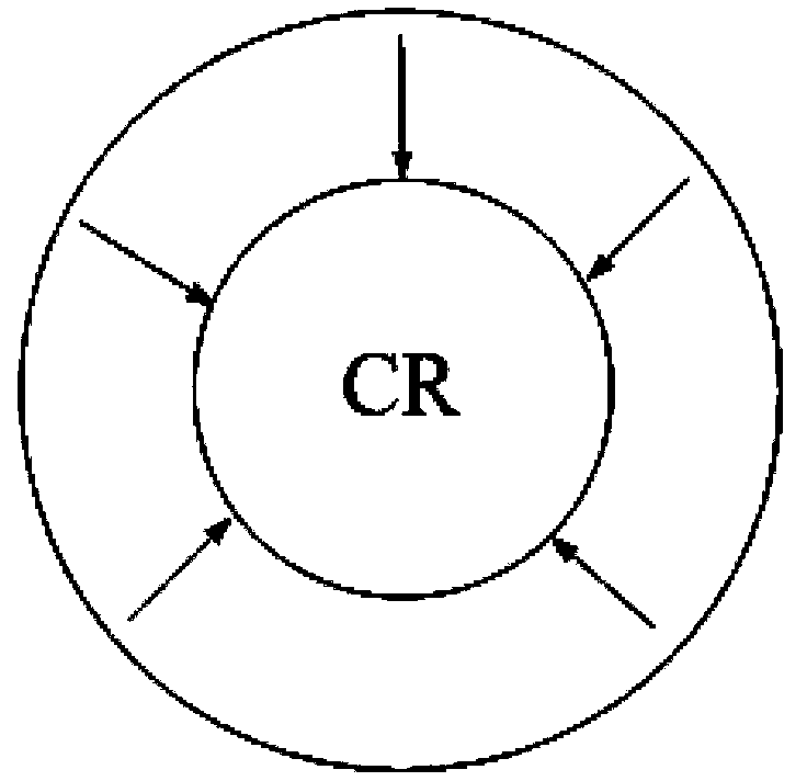
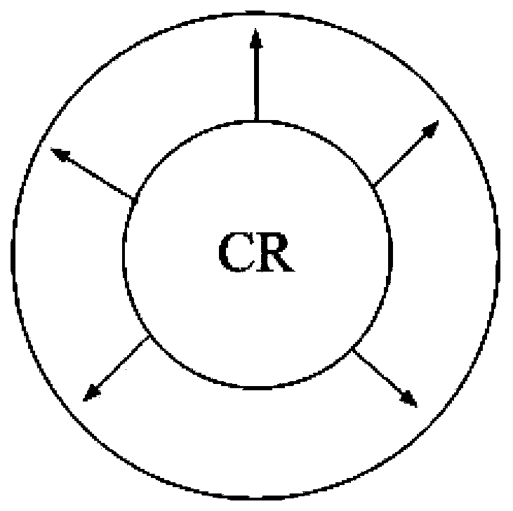
[0036] It can be seen from Figure 1 that a hollow cylindrical magnet (permanent magnet or superconducting block) is obtained by radial magnetization, and Figure 2 shows the distribution of magnetic force lines of the magnet, and the direction of the magnetic force lines is from the inside to the outside (ie The inner surface is N pole and the outer surface is S pole), or from the outside to the inside (that is, the outer surface is N pole and the inner surface is S pole), the magnetic field inside and outside the magnet is unidirectional and uniform. For ease of illustration and representativeness, the hollow cylindrical magnets mentioned below are permanent magnets or superconducting bulk materials.

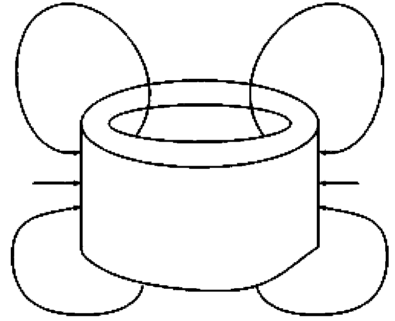
[0037] attached Figure 14 with attached Figure 15 The internal magnetic circuit of the motor is analyzed with the example that the ou...

Embodiment approach 1

[0038] Implementation Mode 1: Refer to the attached Figure 4 The overall axial sectional view of the middle motor, the specific implementation method of scheme one is: as shown in Figure 3, the squirrel-cage structure of the armature part is shown in the figure, including the squirrel-cage conductor 1 and the collector end ring 2, the squirrel-cage structure Both the cage conductor and the collector end ring are made of conventional materials (such as copper or cast aluminum), and the squirrel cage conductor 1 is inserted into the collector end ring 2 to form the armature part. The collector end rings 2 at both ends of the armature part lead out the current inflow path 601 and the current outflow path 602 respectively, and lead out the induced current to the terminal 603 outside the motor casing. The excitation part adopts the hollow cylindrical permanent magnet 3, which is closely connected with the rotating shaft 5 through the laminated silicon steel sheet 4 to form the exc...

Embodiment approach 2

[0039] Embodiment 2: The materials and components used in Embodiment 2 are exactly the same as those in Embodiment 1, and the structure has been adjusted. The difference from Embodiment 1 is that the excitation part is fixed, and the armature part rotates with the shaft. The excitation part adopts a hollow cylindrical permanent magnet 3, which is fixed inside the motor casing 6 to generate a static magnetic field in space. The inner magnetic field of the hollow cylindrical permanent magnet is a unidirectional, uniform and constant magnetic field. The armature part is located on the rotating shaft, and the squirrel-cage structure of the armature part is shown in Figure 3, in which the squirrel-cage conductor 1 and the collector end ring 2 are closely connected to the rotating shaft 5 through the laminated silicon steel sheet 4. In particular, the collector The brush device 9 is specially designed and manufactured on both sides of the end ring 2. One end of the brush device 9 is ...


PUM


Abstract

The invention is to provide a DC (direct current) motor without a reversing device. The DC motor comprises a housing, an armature portion, an excitation portion and a rotating shaft. The armature portion and the excitation portion are combined into a working portion and then the working portion is arranged in the housing. The rotating shaft penetrates through the housing and the working portion. The inner layer of the working portion is connected with the rotating shaft to form a one piece and follows the rotating shaft to rotate. The armature portion comprises a squirrel-cage bar conductor and collector end rings, wherein the squirrel-cage bar conductor is inserted into the left and right collector end rings. A current input pathway and current output pathway are arranged in the housing. The housing is externally provided with a connection terminal. The current input pathway and the current output pathway are connected with the connection terminal. In the DC motor, the reversing device is saved and even a brush gear is saved; energy utilization efficiency in the electromechanical conversion process is improved; and reliability of the motor is improved.

Description

technical field [0001] The invention relates to a motor, specifically a DC motor. Background technique [0002] At present, regardless of the AC generator or DC generator, the current generated by the armature part through electromagnetic induction is almost always AC. The existing DC generators use commutators (and brushes) because of the alternating induction current generated inside the motor. ) The device is designed to ensure that the output current is in a single direction, that is, it outputs direct current. When the motor rotates, it is easy to generate heat due to the friction of the brushes. The commutator of the DC generator will also generate electric sparks as the motor speed increases and the current increases. These unfavorable factors limit the design and manufacture of large-capacity DC generators. In addition, although with the development of power electronics technology in recent years, new brushless DC motors replace traditional commutator equipment by...

Claims


Application Information

Patent Timeline
IPC IPC(8): H02K29/00H02K1/27H02K55/00
CPCY02E40/62Y02E40/60
Inventor 程鹏王庚兰海张敬南黄曼磊刘宏达张强秦鹏李峰岩宋首男
Owner HARBIN ENG UNIV
Why Eureka
Try Eureka