Synchronous oscillator circuit

A technology of synchronous oscillation and circuit, applied in the direction of electrical components, automatic power control, etc., can solve problems affecting the overall performance of electronic systems, difference frequency noise, intermodulation interference, etc., to solve electromagnetic interference, reduce interference, and solve switching noise Effect

Inactive Publication Date: 2013-11-20
UNIV OF ELECTRONIC SCI & TECH OF CHINA
View PDF2 Cites 11 Cited by
  • Summary
  • Abstract
  • Description
  • Claims
  • Application Information

AI Technical Summary

Problems solved by technology

[0004] However, usually different components in an electronic system have their own specific frequency oscillators, resulting in problems such as intermodulation in

Method used


Image

  • Synchronous oscillator circuit
  • Synchronous oscillator circuit
  • Synchronous oscillator circuit

Examples


Embodiment Construction

[0018] specific implementation plan

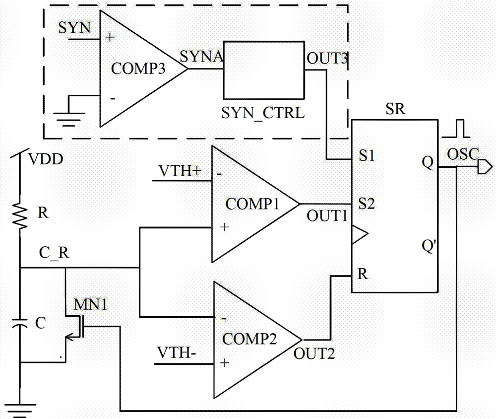
[0019] like figure 2 As shown, the synchronous oscillator circuit of the present invention includes a first comparator COMP1, a second comparator COMP2, a third comparator COMP3, a synchronous control circuit SYN_CTRL, an SR latch, an NMOS transistor MN1, a resistor R, and a capacitor C.

[0020] The negative input terminal of the third comparator COMP3 is grounded, the positive input terminal is connected to the synchronous input signal SYN, and the output terminal is connected to the input terminal of the synchronous control circuit SYN_CTRL. The output end of the synchronous control circuit SYN_CTRL is connected to the S1 end of the SR latch. One end of the resistor R is connected to the power supply VDD, and the other end is connected to the capacitor C. The other end of the capacitor C is grounded. The drain of the NMOS transistor MN1 is connected to the common terminal of the resistor R and the capacitor C, the source is grounded...


PUM


Abstract

The invention relates to a synchronous oscillator circuit which forces synchronization according to an external input synchronous signal. The invention discloses the synchronous oscillator circuit for solving the problems associated with frequency, such as electromagnetic interference, switch noise of the circuit, and the problem of improving the stability of clock signal of the circuit. The technical scheme is as follows: the synchronous oscillator circuit comprises a first comparator, a second comparator, a third comparator, a synchronous control circuit, an SR latch, an NMOS (N-channel Metal Oxide Semiconductor) tube, a resistor and a capacitor. The synchronous oscillator circuit in a work mode of controlling inner frequency of the circuit by the external period signal has the characteristic of high stability, and can solve the problems associated with frequency, such as the electromagnetic interference and the switch noise of the circuit,. The circuit has the characteristics of simple structure, easiness in transplanting and adjustability of external frequency, and can be widely applied to various functional circuits, and in particular to a switch power supply to reduce interference to the circuit when the switch power supply works at certain frequency.

Description

technical field [0001] The invention relates to integrated circuit technology, in particular to a synchronous oscillator circuit forcibly synchronous according to an external input synchronous signal. Background technique [0002] In electronic systems, the role of the oscillator is usually to provide a clock signal for the circuit system, coordinate the dynamic work of the circuit system, and is an indispensable power module. [0003] Traditional oscillator circuits such as figure 1 As shown, the capacitor C is the charging and discharging capacitor, R is the current limiting resistor, the upper threshold voltage VTH+ and the lower threshold VTH- are the reference voltages of the comparator COMP1 and the comparator COMP2 respectively. The oscillator compares the voltage on the capacitor C with the two reference voltages VTH+ and VTH- of the comparator, periodically changes the state of the SR latch, controls the turn-on and turn-off of the NMOS transistor MN1, and forms an...

Claims


Application Information

Patent Timeline
IPC IPC(8): H03L7/06
Inventor 周泽坤张庆岭张其营薛晓满崔佳男石跃明鑫王卓张波
Owner UNIV OF ELECTRONIC SCI & TECH OF CHINA
Why Eureka
Try Eureka