Micropower heat dissipating cabinet

A technology of micro-power consumption and cabinets, which is applied in cooling/ventilation/heating transformation, electrical equipment shells/cabinets/drawers, electrical components, etc., and can solve the problems of increasing the power of a single cabinet, distributing difficult cabinets on demand, and difficult to install air conditioners, etc. problem, to achieve the effect of increasing installed power, saving energy consumption, and high exhaust temperature

Inactive Publication Date: 2013-11-20
CHINA INFOMRAITON CONSULTING & DESIGNING INST CO LTD
View PDF3 Cites 11 Cited by
  • Summary
  • Abstract
  • Description
  • Claims
  • Application Information

AI Technical Summary

Problems solved by technology

[0004] There are some problems in this traditional computer room cooling method, mainly as follows: (1) Since the power of each cabinet in the computer room is not exactly the same, it is difficult to distribute the air to the computer room in the traditional way after centralized treatment of the air. need to be assigned
At the same time, due to the increase in the power of a single cabinet, the use of the traditional air-conditioning system dedicated to the computer room is prone to local overheating in the computer room, whether it is up-supply or down-supply.
(2) Since the power of a single cabinet is too large, it is necessary to configure more dedicated air conditioners for the computer room, especially in some high-level and high-security computer rooms with many redundant backup air conditioners. Required number of air conditioners
(3) When the outdoor temperature is lower than the indoor temperature of the computer room, the compressor is still used for cooling, which wastes a lot of energy

Method used


Image

  • Micropower heat dissipating cabinet
  • Micropower heat dissipating cabinet
  • Micropower heat dissipating cabinet

Examples


Embodiment 1

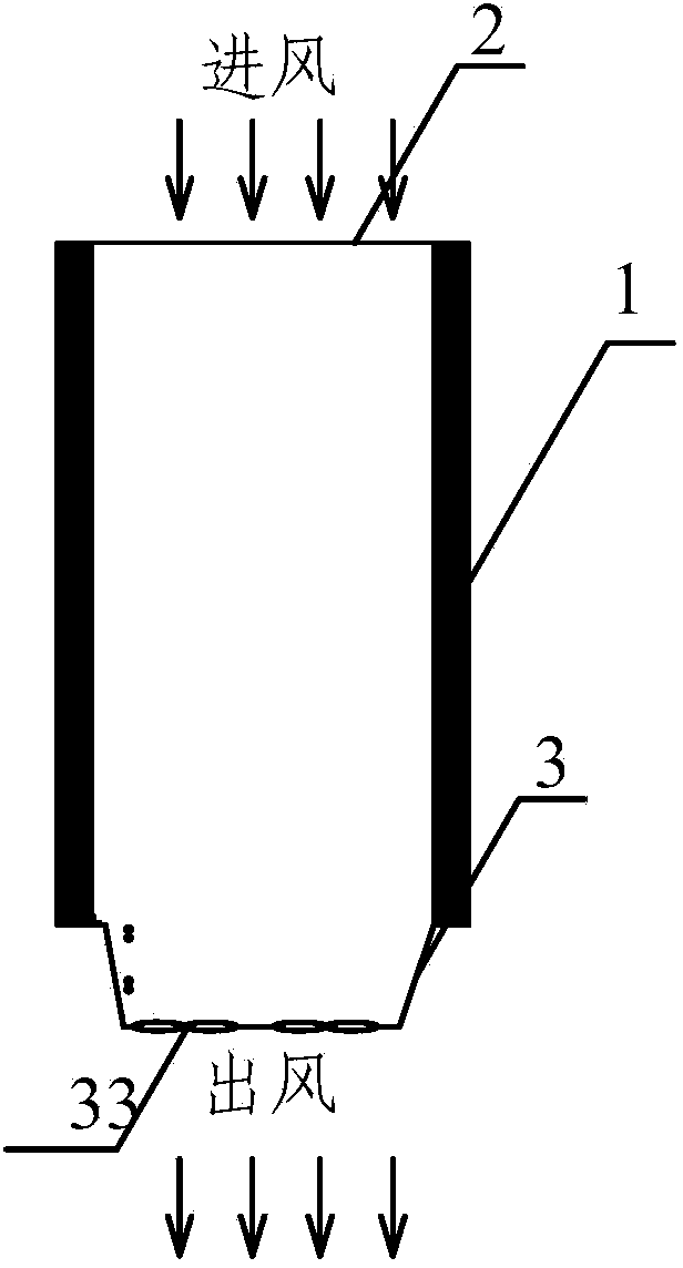
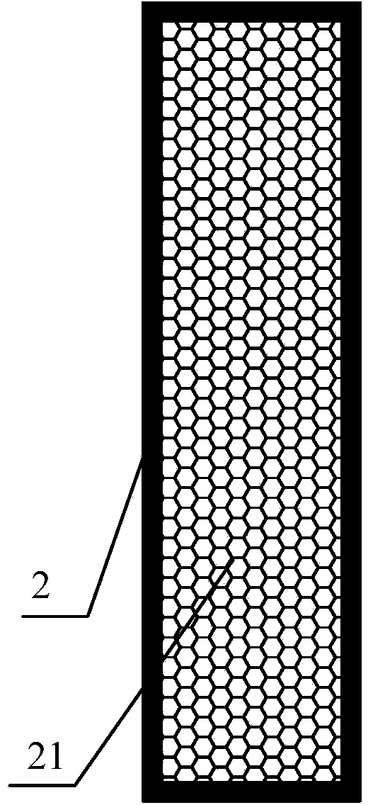
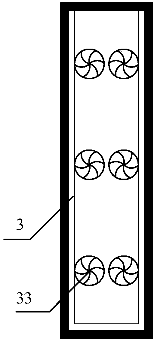
[0028] Such as Figure 1~4 as well as Figure 7 As shown, this embodiment includes a cabinet body 1, a cabinet front door 2, a cabinet back door 3, a first microchannel heat exchanger 31, a second microchannel heat exchanger 32, a fan 33, a water collecting tray 34, a first The refrigerant pipe interface 35 of the first microchannel heat exchanger, and the refrigerant pipe interface 36 of the second microchannel heat exchanger. The front door 2 of the cabinet is provided with a honeycomb vent 21 .

[0029] In this implementation, when the computer room is normally installed and running, the cabinet body 1 is used to install electronic information equipment, and the first microchannel heat exchanger refrigerant pipe interface 35 and the second microchannel heat exchanger in the cabinet back door 3 The refrigerant pipe interface 36 of the heat exchanger is respectively connected to two sets of water Freon heat exchangers in the external system, and there is a certain height di...

Embodiment 2

[0032] Such as Figure 5 As shown, in this embodiment, the width of the first microchannel heat exchanger is equal to the width of the second microchannel heat exchanger, and all air first passes through the first microchannel heat exchanger before entering the second microchannel heat exchanger. Heater, all the other are identical with embodiment 1.

Embodiment 3

[0034] Such as Figure 6 As shown, the width of the first microchannel heat exchanger in this embodiment is equal to the width of the second microchannel heat exchanger, but there is a gap space in the middle of the first microchannel, and part of the air can directly enter the second microchannel through the gap space. Two micro-channel heat exchangers, part of the air can be directly discharged to the machine room from both sides through the first micro-channel heat exchanger, part of the air first passes through the first heat exchanger and then passes through the second heat exchanger, and the rest Example 1 is the same.


PUM


Abstract

The invention discloses a micropower heat dissipating cabinet, which comprises a cabinet body used for placing electronic equipment, a cabinet main door and a cabinet backdoor, wherein honeycomb ventilation holes are formed in the cabinet main door; the cabinet backdoor is provided with fans; one or more micro-channel heat exchangers are arranged on side, close to the cabinet backdoor, of the cabinet body; a refrigerant pipe joint for connecting external water and Freon heat exchangers are arranged on each micro-channel heat exchanger; ventilation holes or ventilation gaps are formed in each micro-channel heat exchanger; a water-collection tray is arranged below the micro-channel heat exchangers. The cabinet solves the problems existed in a project or an air condition system of a conventional machine room, releases machine room air-conditioner zone area for mounting electronic information equipment, improves the utilization ratio of the machine room, improves the heat exchange temperature difference and can extend the use time of outdoor cold sources as the air exhausting temperature of the cabinet is high, and greatly saves the energy consumption of the air condition system.

Description

technical field [0001] The invention relates to a cooling cabinet, in particular to a cooling cabinet with low power consumption used in an electronic information machine room. Background technique [0002] With the development of society and economy, the degree of informatization continues to increase, especially with the development of cloud computing, Internet, e-commerce, Internet of Things and other technologies, both communication operators, governments, and enterprises need to build a large number of electronic information rooms including The data center serves as the basic support. The electronic information room is a place for installing electronic information equipment and its supporting equipment, such as data equipment, which generates a lot of heat. With the technical development of electronic information equipment in recent years, the power of a single cabinet has been continuously increased. [0003] Traditional cabinets for electronic information equipment ...

Claims


Application Information

Patent Timeline
Patent Type & Authority Applications(China)
IPC IPC(8): H05K5/00H05K7/20
Inventor 潘劲松张川燕张津京
Owner CHINA INFOMRAITON CONSULTING & DESIGNING INST CO LTD
Why Eureka
Try Eureka