Check patentability & draft patents in minutes with Patsnap Eureka AI!

Liquefied gas regasification device and regasification gas manufacturing method

A technology of liquefied gas and regasification, which is applied to container discharge methods, gas/liquid distribution and storage, gas treatment/storage effects, etc., can solve problems such as difficult miniaturization, achieve simple structure, and reduce the possibility of freezing Effect

Active Publication Date: 2016-06-22
MITSUBISHI SHIPBUILDING CO LTD
View PDF5 Cites 0 Cited by
  • Summary
  • Abstract
  • Description
  • Claims
  • Application Information

AI Technical Summary

Problems solved by technology

However, there are the following problems: it requires a large amount of seawater, and it is necessary to ensure a heat transfer area for the flow of seawater, so it is difficult to miniaturize
Therefore, the ORV method is difficult to install on offshore floating bodies such as FSRU (Floating Storage and Regasification Unit) and FPSO (Floating Production Storage and Offloading) and LNG ships.

Method used


Image

  • Liquefied gas regasification device and regasification gas manufacturing method
  • Liquefied gas regasification device and regasification gas manufacturing method
  • Liquefied gas regasification device and regasification gas manufacturing method

Examples


no. 1 Embodiment approach )

[0044] The first embodiment of the present invention will be described below.

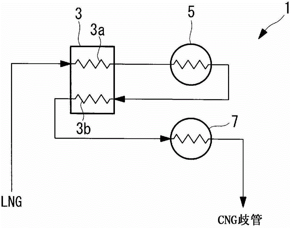
[0045] Install LNG storage equipment (liquefied gas storage equipment) on ships such as FSRU (Floating Storage and Regasification Unit) and FPSO (Floating Production Storage and Offloading), floating bodies at sea, and LNG ships. figure 1 A regasification apparatus 1 is shown for performing regasification when supplying LNG (liquefied gas) derived from an LNG storage tank (liquefied gas storage tank) of the LNG storage facility to a desired place.

[0046] Such as figure 1 As shown, the regasification device 1 has: a preheating heat exchanger 3 for preheating LNG; a first shell-and-tube heat exchanger (first heat exchanger) 5 for preheating The liquefied gas is regasified using seawater or clean water; the second shell-and-tube heat exchanger (second heat exchanger) 7 regasifies the liquefied gas introduced from the preheating heat exchanger 3 using seawater or clean water.

[0047] The heat ex...


PUM


Abstract

A liquefied gas regasification plant which can regasify liquefied gas by a shell-and-tube-type heat exchanger with a simple configuration by preheating the liquefied gas with a simple configuration is provided. The liquefied gas regasification plant includes a preheating heat exchanger (3) that preheats LNG flowing through a preheated flow (3a) by gasification gas flowing through a preheating flow (3b), and a first shell-and-tube-type heat exchanger (5) that regasifies the LNG preheated in the preheating heat exchanger (3) by seawater or fresh water, the gas regasified in the first shell-and-tube-type heat exchanger (5) being guided to the preheating flow (3b), the liquefied gas regasification plant further including a second shell-and-tube-type heat exchanger (7) that regasifies the LNG condensed through the preheating flow (3b) by seawater or fresh water.

Description

technical field [0001] The invention relates to a regasification device for regasifying liquefied gas such as LNG and a method for producing the regasification gas. Background technique [0002] A regasification device is used to regasify LNG (liquefied natural gas) stored in a tank and deliver it to the desired location. As such a regasification device, an open-type vaporizer (ORV: Open-Rack-type Vaporizer) system is often used (for example, refer to the following Patent Document 1). In this ORV system, seawater is used as a heat source, and the seawater is sprayed in the air on the outer surfaces of a plurality of heat transfer tubes arranged in a plate shape to vaporize the LNG inside the heat transfer tubes. However, there are problems in that a large amount of seawater is required, and it is necessary to secure a heat transfer area for the seawater to flow, so it is difficult to downsize. Therefore, the ORV method is difficult to install on ships such as FSRU (Floatin...

Claims


Application Information

Patent Timeline
IPC IPC(8): F17C9/04
CPCF17C7/04F17C2201/052F17C2221/033F17C2223/0161F17C2223/033F17C2225/0123F17C2225/035F17C2225/036F17C2227/0135F17C2227/0316F17C2227/0318F17C2227/0393F17C2265/033F17C2265/05F17C2270/0105
Inventor 冈胜
Owner MITSUBISHI SHIPBUILDING CO LTD
Features
  • R&D
  • Intellectual Property
  • Life Sciences
  • Materials
  • Tech Scout
  • Unparalleled Data Quality
  • Higher Quality Content
  • 60% Fewer Hallucinations
Learn More