Automatic feeding machine structure

A feeder, automatic technology, applied in the field of automatic feeder structure, can solve the problems of increased labor intensity, artificial damage of materials, low degree of automation, etc., and achieves the effect of saving manpower, good processing quality, and reducing labor intensity

Inactive Publication Date: 2013-11-27
钱旭荣
View PDF7 Cites 12 Cited by
  • Summary
  • Abstract
  • Description
  • Claims
  • Application Information

AI Technical Summary

Problems solved by technology

If manual transfer is used for loading and unloading operations, although it can ensure that the plates are placed neatly, manual transfer and

Method used


Image

  • Automatic feeding machine structure

Examples


Example Embodiment

[0019] The present invention will be further described in detail below with reference to the drawings and specific embodiments.

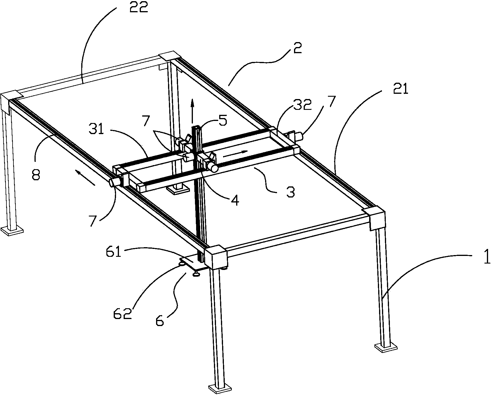
[0020] Such as figure 1 As shown, the automatic feeder structure of the present invention includes a frame, the frame includes a column 1, a balanced beam 21 arranged on the column, and also includes a movable frame and its moving device, a lifting beam and its lifting device, The adsorption device 6, the mobile device is fixed on the mobile frame and allows the mobile frame to move relative to the cross beam, the lifting device is fixed on the mobile frame and allows the lifting beam 5 to move up and down relative to the mobile frame, and the adsorption device 6 is fixed on Below the lifting beam 5. As a result, the lifting beam moves horizontally in the front, back, left, and right directions along with the moving frame and vertically lifts and lowers itself on the moving frame, thereby forming a compound motion of three-dimensional displacement. T...


PUM


Abstract

The invention discloses an automatic feeding machine. The automatic feeding machine comprises a machine frame, wherein the machine frame comprises stand columns, balancing transverse beams arranged on the stand columns, moving racks, moving devices of the moving racks, a lifting beam, a lifting device of the lifting beam and an absorption device, the moving devices are fixed on the moving racks and enable the moving racks to move relative to the transverse beams, the lifting device is fixed onto the moving racks and enables the lifting rack to move vertically relative to the moving racks, and the absorption device is fixed below the lifting beam. The automatic feeding machine is simple and reasonable in structure, convenient to operate and use, safe in operation and usage, good in processing quality and high in work efficiency; meanwhile, saves manpower, reduces labor intensity of operators and is safe and reliable in operation.

Description

technical field [0001] The invention relates to the technical field of woodworking machinery, and more specifically relates to an automatic feeding machine structure. Background technique [0002] In the field of woodworking machinery, before and after the processing of wood and boards, the boards need to be transported to a specific position. Some large-sized, thin-sheet finished products and semi-finished products are also required to be stacked neatly to facilitate the processing of the next process. For example, the loading and unloading operation by manual transfer can ensure that the plates are placed neatly, but manual transfer and unloading may easily cause artificial damage to the materials, and increase the labor intensity of personnel, and the degree of automation is low. Contents of the invention [0003] In order to solve the above existing problems, improve production efficiency, and reduce labor intensity of workers, the present invention uses technologies s...

Claims


Application Information

Patent Timeline
IPC IPC(8): B65H5/08B65H29/32
Inventor 钱旭荣
Owner 钱旭荣
Why Eureka
Try Eureka