Sieve plate-free fluidizing chlorination furnace

A technology of fluidized chlorination furnace without sieve plate, which is applied in the direction of titanium halide, etc., can solve the problems of destroying the normal production of the upper slag discharge chlorination furnace, achieve the effect of prolonging the continuous operation time, expanding the scope of application of raw materials, and overcoming harsh requirements

Active Publication Date: 2013-11-27
甘肃德通国钛金属有限公司 +1
View PDF6 Cites 8 Cited by
  • Summary
  • Abstract
  • Description
  • Claims
  • Application Information

AI Technical Summary

Problems solved by technology

Due to the relatively high content of CaO and MgO in domestic titanium raw materials, the CaCl produced by the chlorination reaction 2 , MgCl 2 It is in a liquid state within the operating temperature range of the chlorination furnace, which will cause the powdery materials in the fluidized bed to stick to each other to form large particles or agglomerates, which cannot be carried out with the reaction product airflow, and will damage the upper slag discharge chlorination furnace in serious cases normal production

Method used


Image

  • Sieve plate-free fluidizing chlorination furnace
  • Sieve plate-free fluidizing chlorination furnace

Examples


Embodiment Construction

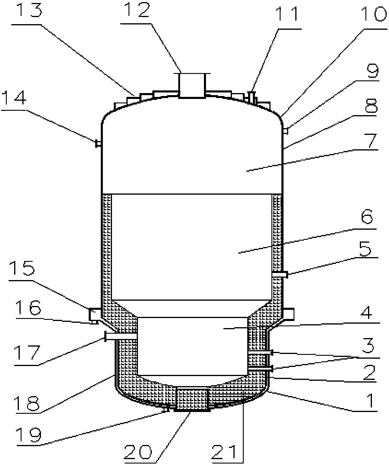
[0018] Such as figure 1 , figure 2 shown. A boiling chlorination furnace without a sieve plate, comprising upper and lower cylinders 8 and 2, the lower cylinder 2 is connected to the bottom of the upper cylinder 8 through a hollow tapered part, and an upper cylinder with an inner cavity is installed on the top of the upper cylinder 8 Head 10, lower head 1 with an inner cavity is installed at the bottom of the lower cylinder 2, wherein the inner cavity of the lower head 1 and the inner cavity of the lower cylinder 2 constitute the chlorine gas inlet chamber 4, the inner cavity of the tapered part, and the upper cylinder 8 The middle and lower part of the inner cavity constitutes the material boiling section 6, the inner cavity of the upper head 10, and the upper part of the inner cavity of the upper cylinder body 8 constitute the gas-solid separation section 7, the chlorine gas inlet chamber 4 is lined with refractory bricks 21, and the chlorine gas inlet chamber 4 is covered...


PUM


Abstract

The invention discloses a sieve plate-free fluidizing chlorination furnace with the function of discharging slag from the upper part and the side of the fluidizing chlorination furnace. The fluidizing chlorination furnace is a tank body which adopts a steel structure and comprises an upper cylindrical cylinder body, a lower cylindrical cylinder body, an upper papilionaceous sealing head and a lower papilionaceous sealing head, wherein the diameter of the upper cylindrical cylinder body is different from that of the lower cylindrical cylinder body. A chlorine gas inlet chamber is arranged at the bottom of the fluidizing chlorination furnace; a material fluidizing section is arranged in the middle of the fluidizing chlorination furnace; a gas-solid separation section is arranged at the upper part of the fluidizing chlorination furnace. The chlorine inlet chamber and the material fluidizing section are lined with refractory bricks; the inner surface of the gas-solid separation section is covered with high-temperature-resistant anti-corrosive composite ceramic paint so as to prevent high-temperature chlorine gas from corroding the gas-solid separation section; a gas outlet is formed in the central position of the upper sealing head; fine-particle slag is discharged from the gas outlet along with airflow after chlorination reactions; a side slag discharge port is formed in the side wall of the upper part of the chlorine gas inlet chamber and used for discharging coarse-particle slag discontinuously; two layers of chlorine gas inlet pipes, which are designed specially, are arranged in the chlorine gas inlet chamber; each chlorine gas inlet pipe orifice is provided with a blowing block joint; the chlorine gas inlet pipes are inserted into the refractory brick layer and extend to the chamber of the fluidizing chlorination furnace; chlorine gas and blowing block airflow are prevented from impacting the refractory brick layer.

Description

technical field [0001] The invention relates to the field of chlorination furnaces, in particular to a boiling chlorination furnace without a sieve plate. Background technique [0002] The boiling chlorination furnace is the main equipment of the titanium tetrachloride preparation process, which belongs to the fluidized bed reactor, has good mass transfer and heat transfer effects, high production capacity, and the equipment is easy to be large-scaled. At present, the boiling chlorination furnaces used at home and abroad are divided into two categories: sieve plate and non-sieve plate. A chlorine gas distribution plate (sieve plate) is installed at the bottom of the fluidized chlorination furnace with a sieve plate. There are hundreds or even hundreds of chlorine holes on the chlorine gas distribution plate. The structure is complex and the manufacturing process requires high requirements. Moreover, the holes of the sieve plate are easily blocked by solid particles falling...

Claims


Application Information

Patent Timeline
Patent Type & Authority Applications(China)
IPC IPC(8): C01G23/02
Inventor 徐兴荣蔡林清解为清吴震坤孙洪涛杨国强刘泳刘海涛
Owner 甘肃德通国钛金属有限公司
Why Eureka
Try Eureka