

Vibrating high burn-out grate
A technology for burning embers and grates, which is applied in the direction of mobile grates, oscillating grates, grates, etc. It can solve the problems of short service life of refractory castable materials, reduce the wear or ablation of grates, and reduce leakage. Slag, reduce the effect of loss on ignition
- Summary
- Abstract
- Description
- Claims
- Application Information
AI Technical Summary
Problems solved by technology
Method used
Image

Examples
Embodiment Construction
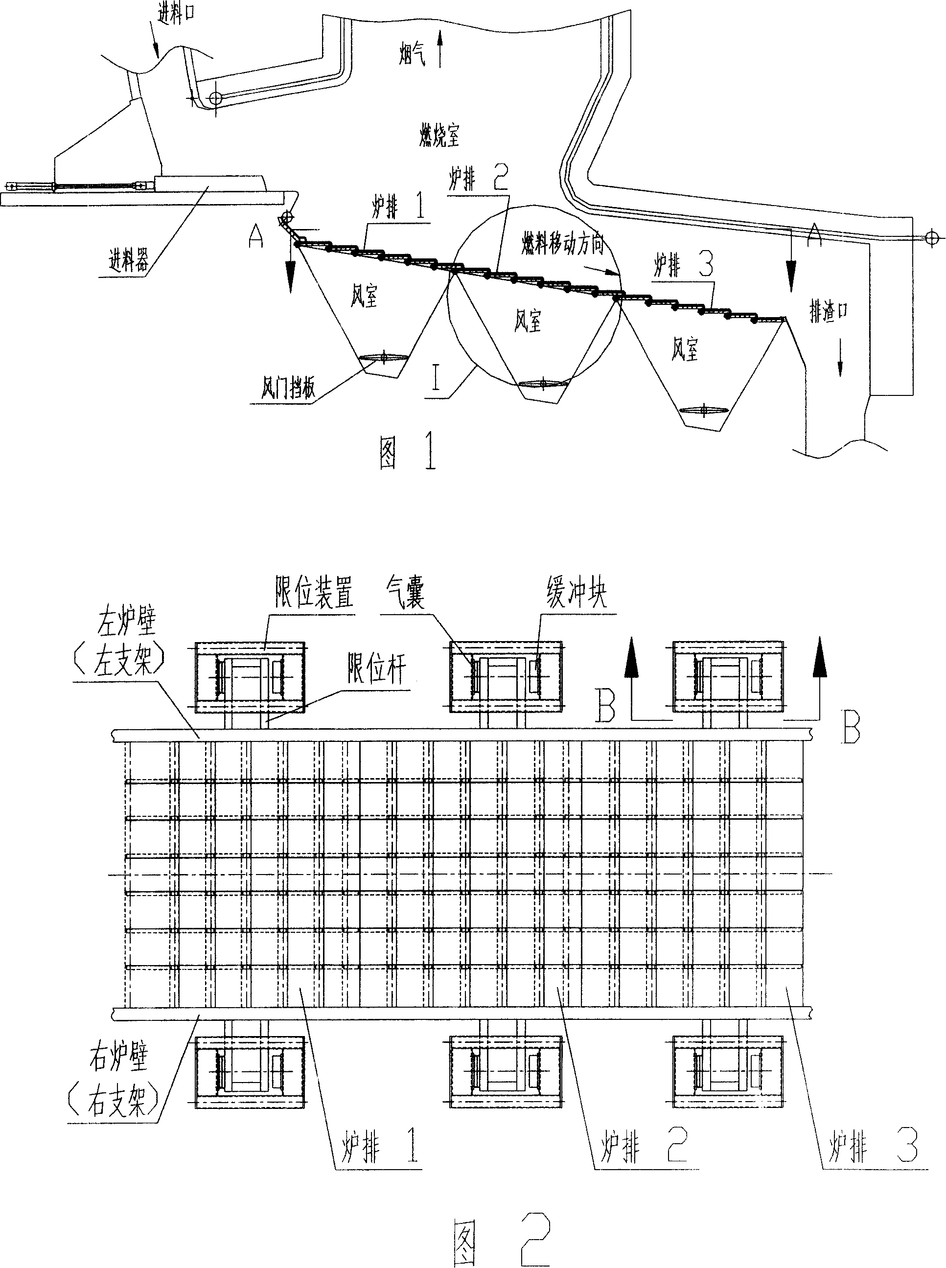
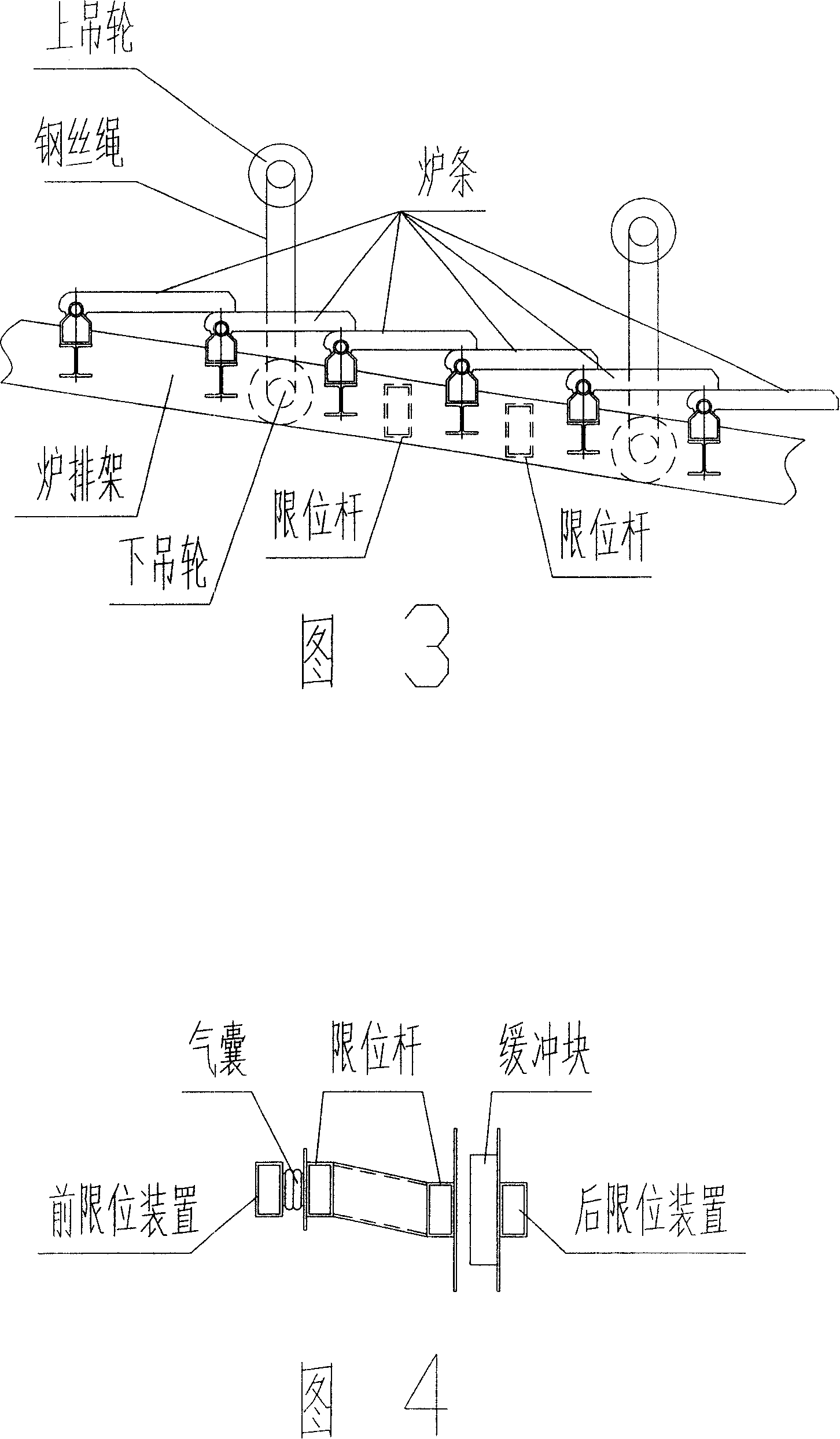
[0022] In the implementation example shown in Figure 1, the incinerated substances are fed into the surface of the grate by the feeder through the feed port, several grates are suspended in the lower part of the combustion chamber by wire ropes, and the incinerated substances that have just entered are arranged on the grate surface. The hot air sent from the air chamber below is used to dry, remove the moisture in it, and at the same time obtain the oxygen required for the combustion reaction, and start the process of ignition, combustion, and embers under the action of radiant heat in the combustion chamber. The damper baffle plate in the air chamber plays the role of adjusting the air volume sent into the fire grate according to the amount of incinerated material on the fire grate surface. During the combustion process, under the vibration of the grate, the incinerated material moves from the front grate to the rear grate. After the combustion is complete, it falls into the ...
PUM
 Abstract
Description
Claims
Application Information