Masonry structure of refractory material in hot-blast stove warm-air pipe ripple compensator

A technology of corrugated compensator and hot blast pipe, which is applied in the field of hot blast stove and hot blast stove in metallurgical industry. Long-term stable work and the effect of improving the overall stability

Active Publication Date: 2013-11-27
BEIJING SHOUGANG INT ENG TECH
View PDF7 Cites 4 Cited by
  • Summary
  • Abstract
  • Description
  • Claims
  • Application Information

AI Technical Summary

Problems solved by technology

[0006] For a long time, the redness of the hot blast pipe compensator has become a difficult problem for produ

Method used


Image

  • Masonry structure of refractory material in hot-blast stove warm-air pipe ripple compensator
  • Masonry structure of refractory material in hot-blast stove warm-air pipe ripple compensator
  • Masonry structure of refractory material in hot-blast stove warm-air pipe ripple compensator

Examples


Embodiment 1

[0026] Figure 2 to Figure 6 It is a specific implementation of the present invention.

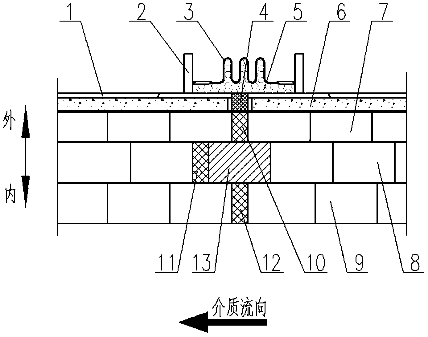
[0027] Depend on figure 2 It can be seen that the masonry structure of the hot air pipeline compensator area of ​​the present invention includes: pipeline steel shell 1, ring plate 2, bellows 3, expansion joint 4, heat insulation layer 5, refractory spray paint 6, first layer of heat insulation brick 7 , the second layer of insulation bricks 8, the first layer of firebricks 9, the expansion joints of the first layer of insulation bricks 10, the expansion joints of the second layer of insulation bricks 11, the expansion joints of the first layer of firebricks 12, special-shaped refractory Brick 14, diversion brick 15.

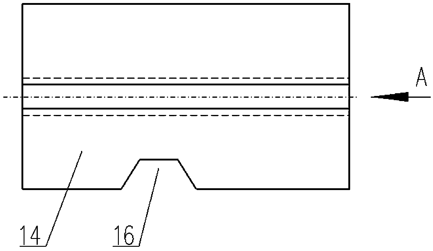
[0028] Depend on image 3 , Figure 4 It can be seen that the special-shaped refractory brick 14 has a first groove 16, the groove form is semicircular or square or trapezoidal, the first boss 17, the boss form is semicircular or square or trapezoidal, the second groove 1...

Embodiment 2

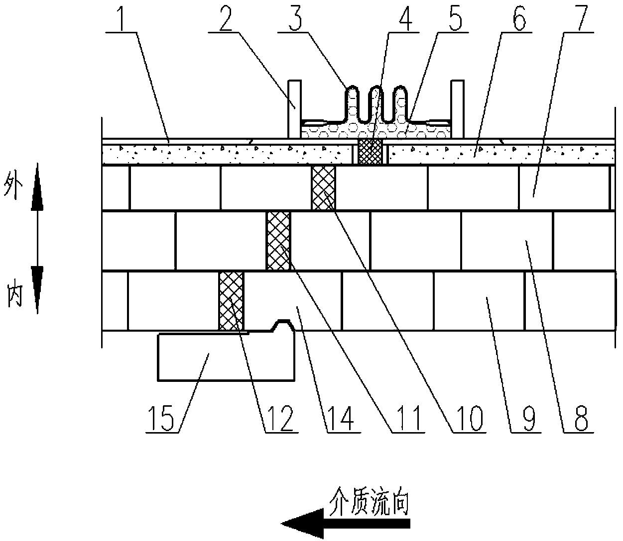
[0035] In this implementation, the masonry structure in the hot air duct compensator area is figure 2 similar. This embodiment can be adopted when the temperature of the gas medium in the hot air duct is relatively low and only one layer of heat insulating bricks can be built.

[0036] At this time, the masonry structure of the hot air pipeline compensator area of ​​the present invention includes: pipeline steel shell 1, ring plate 2, bellows 3, expansion joint 4, heat insulation layer 5, refractory spray paint 6, first layer of heat insulation brick 7 , the first layer of refractory bricks 9, the expansion joints 10 of the first layer of insulating bricks, the expansion joints 12 of the first layer of refractory bricks, special-shaped refractory bricks 14, and diversion bricks 15.

[0037] The special-shaped refractory brick 14 has a first groove 16, the groove form is semicircular or square or trapezoidal, the first boss 17, the boss form is semicircular or square or trape...


PUM


Abstract

The invention discloses a masonry structure of a refractory material in a hot-blast stove warm-air pipe ripple compensator and belongs to the technical field of a hot-blast stove in a metallurgy industry. The masonry structure comprises a pipe steel casing, an annular plate, bellows, an expansion joint, a thermal insulation layer, a refractory spraying material, a first heat-insulating brick layer, a second heat-insulating brick layer, a first refractory brick layer, a first heat-insulating brick expansion joint, a second heat-insulating brick expansion joint, a first refractory brick expansion joint, special-shaped refractory bricks and diversion bricks. The masonry structure has the advantages that the diversion bricks can effectively protect a refractory fiber blanket filled in the expansion joints so that it is avoided that the refractory fiber blanket in a warm-air pipe is carried by high-temperature high-pressure air flows in work; under the dual action of the diversion bricks and the hot pressing, the refractory fiber blanket can stably work for a long time, absorb the heat expansion and protect the bellows; the reverse maze expansion joint is arranged in an air flow reverse direction so that the expansion joint enters into the bellows difficultly and multi-protection of the bellows is realized; and interlocking of the refractory bricks, the special-shaped refractory bricks and the diversion bricks improves integral masonry stability so that the bellows can stably work for a long time.

Description

technical field [0001] The invention belongs to the technical field of hot blast stoves in the metallurgical industry, and in particular provides a masonry structure of refractory materials inside the corrugated compensator of the hot blast pipe of the hot blast stove, which is suitable for hot blast stoves used in blast furnace ironmaking and smelting reduction ironmaking in the ironmaking process . It can also be used in other industrial technical fields that need to heat the gaseous medium to above 1000°C. Background technique [0002] It has been nearly 200 years of history to use hot blast stove to heat blast in blast furnace ironmaking. After heating, the blast temperature is only 149°C at first. With the continuous advancement of technology, the current maximum wind temperature has reached 1350 °C. The increase of air temperature can greatly reduce the coke ratio, save coke, increase the output of blast furnace, and make full use of blast furnace gas with low calori...

Claims


Application Information

Patent Timeline
IPC IPC(8): C21B9/06C21B9/10
Inventor 张福明毛庆武李欣梅丛华银光宇许云曹朝真胡祖瑞孟玉杰杨森
Owner BEIJING SHOUGANG INT ENG TECH
Why Eureka
Try Eureka