Hood-type annealing furnace device

A bell-type annealing furnace and bell-type furnace technology, applied in the direction of bell-type furnaces, furnaces, furnace types, etc., can solve the problems of complex protective gas preparation, heating and transportation processes, heat not being used, and long heat treatment time. Achieve the effect of improving heat transfer efficiency, improving thermal efficiency and enterprise economic benefits, and reducing energy consumption

Inactive Publication Date: 2013-11-27
SHIJIAZHUANG XINHUA IND FURNACE CO LTD
View PDF5 Cites 1 Cited by
  • Summary
  • Abstract
  • Description
  • Claims
  • Application Information

AI Technical Summary

Problems solved by technology

The disadvantages of the existing steel bell furnace annealing are: the heat is not used, resulting in a waste of energy
However, this patent requires complex protective gas preparation, heating and transportation processes, and the heat treatment takes a long time

Method used


Image

  • Hood-type annealing furnace device
  • Hood-type annealing furnace device

Examples


Embodiment 1

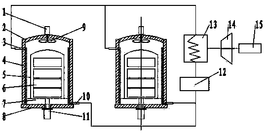
[0014] Bell type annealing furnace device of the present invention such as figure 1 As shown, it consists of 2 bell furnaces, heat transfer oil pump 12, steam generator 13, steam turbine 14 and generator 15. The bell-type furnace includes a hearth 8, a heating mantle, a cooling mantle 2 and an inner cover 5. A support plate 7 is arranged on the upper part of the hearth, and a diversion fan 11 is arranged at the bottom of the hearth. The top of cooling cover 2 is provided with cooling fan 1, and cooling fan is connected with fan 9. The cooling cover is provided with a coil tube 4, and the coil tube is wound on the inner wall of the cooling cover 2, and the coil tube and the jacket are respectively provided with a heat transfer oil outlet 3 and a heat transfer oil inlet 10. The outlet of the heat transfer oil is located at the upper part of the cooling cover, and the inlet of the heat transfer oil is located at the lower part of the cooling cover. The steam generator is a snak...

Embodiment 2

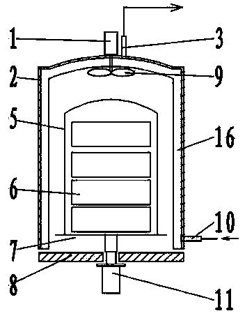
[0017] Another embodiment of this embodiment is as figure 2 As shown, the cooling cover is provided with a jacket 16, the jacket is located on the inner wall and top of the cooling cover, the heat transfer oil outlet 3 of the jacket is located at the top of the cooling cover, and the heat transfer oil inlet 10 is located at the bottom of the cooling cover. Other structures are the same as in Embodiment 1.


PUM


Abstract

The invention relates to a hood-type annealing furnace device, which is composed of 1 to 20 sets of hood-type furnaces, a heat conduction oil pump, a steam generator, a steam turbine and an electric generator, wherein each hood-type furnace comprises a coil base, a heating hood, a cooling hood and an inner hood, a support plate is arranged at the upper part of each coil base, and a diversion draught fan is arranged at the bottom of each coil base; a coiled tube or a jacket is arranged on the cooling hood, and a heat conduction oil outlet and a heat conduction oil inlet are arranged in the coiled tube or the jacket respectively; the heat conduction oil outlet of the coiled tube or the jacket is connected to the inlet of the heat conduction oil pump via the steam generator, and the outlet of the heat conduction oil pump is connected to the heat conduction oil outlet of the coiled tube or the jacket; the steam outlet of the steam generator is connected to the steam inlet of the steam turbine, and the steam turbine is coaxially connected with the electric generator. Due to arrangement of the coiled tube or the jacket in the cooling hood, the heat released during cooling process of the annealing furnace is taken out by circulation of the heat conduction oil in the coiled tube or the jacket and is used for electricity generation, so that the heat during heat treatment process of metal materials can be fully utilized, the energy consumption is lowered, and the thermal efficiency of heat treatment of metals and the economic benefit of enterprises are improved.

Description

technical field [0001] The invention belongs to the technical field of heat treatment of metal materials, and relates to a bell annealing furnace device, in particular to a bell annealing furnace device capable of generating electricity with waste heat. Background technique [0002] Material annealing mainly has two basic functions, one is to eliminate the hardening and residual stress generated during processing, soften the material, improve plasticity, and facilitate further processing; the other is to change the structure of the material to obtain the required grain size and grain size. Orientation. Bell furnace annealing is one of the main technologies for heat treatment of cold-rolled steel. It is to stack several coils of steel into stacks, cover them with a protective cover, heat them up, and cool them after reaching the specified annealing temperature. Generally, the annealing of the bell furnace adopts the single-stack or multi-stack type. After the steel is stacke...

Claims


Application Information

Patent Timeline
Patent Type & Authority Applications(China)
IPC IPC(8): C21D1/00C21D1/26F27B11/00
Inventor 贾会平
Owner SHIJIAZHUANG XINHUA IND FURNACE CO LTD
Why Eureka
Try Eureka