An electronically controlled unit combination pump for light vehicle diesel engine

A combined pump and single pump technology, applied in mechanical equipment, engine components, machines/engines, etc., can solve problems such as affecting service life, insufficient oil absorption, large cam impact, etc., to ensure working stability and shorten the overall length , the effect of reducing inertia

Active Publication Date: 2015-12-09
龙口龙泵柴油喷射高科有限公司
View PDF6 Cites 0 Cited by
  • Summary
  • Abstract
  • Description
  • Claims
  • Application Information

AI Technical Summary

Problems solved by technology

However, when the existing electronically controlled combined pump is applied to a high-speed diesel engine, there are still the following defects. The first is that the length and quality of the tappet are relatively large, the structure is unreasonable, and the impact on the cam is large during high-speed operation; Because the arc line corresponding to the descending section of the plunger in the existing cam is a circular arc transition, the plunger descends at a relatively high speed in the descending section, resulting in a vacuum in the oil suction chamber, resulting in insufficient oil absorption, which makes it easy for the oil pump to The oil is unstable, which leads to unstable operation of the engine; the third is that the relative movement of the roller and the roller pin wears quickly, which affects the service life

Method used


Image

  • An electronically controlled unit combination pump for light vehicle diesel engine
  • An electronically controlled unit combination pump for light vehicle diesel engine
  • An electronically controlled unit combination pump for light vehicle diesel engine

Examples


Embodiment Construction

[0025] The principles and features of the present invention will be described below with reference to the accompanying drawings. The examples are only used to explain the present invention, but not to limit the scope of the present invention.

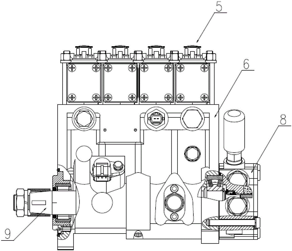
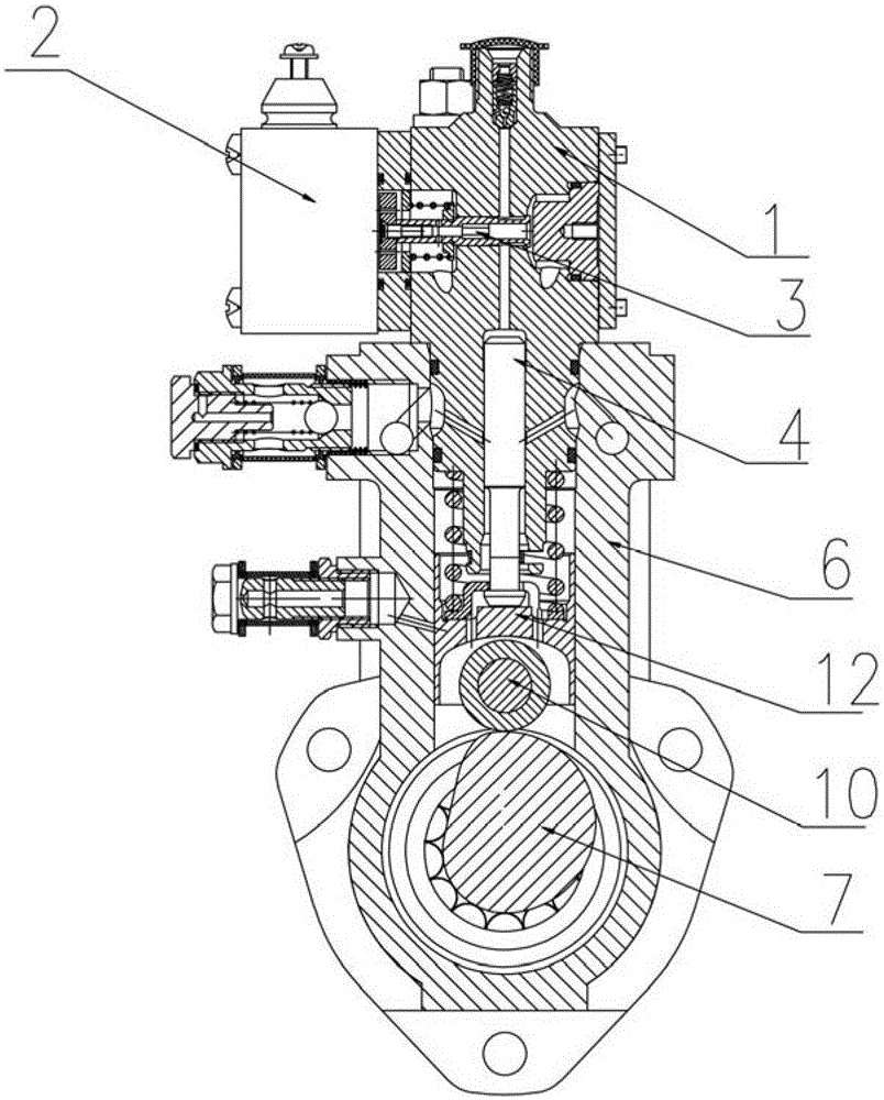
[0026] like figure 1 and Figure 4 As shown, an electronically controlled unit combination pump for a light-duty vehicle diesel engine includes a combined pump body 6, an oil transfer pump 8, a camshaft 9, a plurality of electronically controlled unit pumps 5 and a phase with the electronically controlled unit pump 5. The corresponding tappet assembly and cam 7 are characterized in that the electronically controlled unit pump 5 is installed on the combined pump body 6, and the electronically controlled unit pump 5 includes a unitary pump body 1 and a The plunger 4, the control valve core 3 and the electromagnet 2 installed on one side of the single pump body 1, the oil delivery pump 8 is installed on one side of the combined pump body ...


PUM


Abstract

The invention relates to the technical field of vehicle engine manufacturing, in particular to an electronic unit composite pump for light-vehicle diesels. The electronic unit composite pump for light-vehicle diesels comprises a composite pump body, an oil conveying pump, a camshaft, a plurality of electronic unit pumps, tappet body assemblies corresponding to the electronic unit pumps and a cam, and is characterized in that the electronic unit pumps are installed on the composite pump body and comprise unit pump bodies, a plunger, control valve elements and electromagnets installed on one sides of the unit pump bodies, the oil conveying pump is installed on one side of the composite pump body, the tappet body assemblies are arranged between the cam and the plunger and comprise tappets, rolling wheels and rolling wheel pins, and U-shaped cavities are formed in the ends where the tappets make contact with the rolling wheels, wherein the plunger and the control valve elements are arranged in the unit pump bodies. The electronic unit composite pump for light-vehicle diesels has the advantages of being more compact in structure and capable of acquiring higher working speed so as to be matched with the high-speed diesels.

Description

technical field [0001] The invention relates to the technical field of vehicle engine manufacturing, in particular to an electronically controlled unit combination pump for a light vehicle diesel engine. Background technique [0002] At present, in the field of low-power and high-speed diesel engines, the fuel injection systems are mainly small in-line pumps and VE pumps. Since these two pumps cannot provide higher injection pressure, it is difficult to meet the requirements of the National IV emission standards. The high-pressure common rail system can provide high injection pressure, but the price is high, the use and maintenance costs are also high, and it cannot meet the needs of users. The electronically controlled combined pump can not only provide a fuel injection pressure of up to 200MPa, but also can realize flexible control of fuel injection timing to meet engine emission requirements, and the manufacturing cost is lower than that of the common rail system, and the...

Claims


Application Information

Patent Timeline
Patent Type & Authority Patents(China)
IPC IPC(8): F02M51/04
Inventor 陈瑞军韩利勇郑建松孟祥义刘本学
Owner 龙口龙泵柴油喷射高科有限公司
Why Eureka
Try Eureka