Drifting-proof rivet bolt and connecting structure

A technology of riveting bolts and displacement, applied in the direction of connecting components, bolts, rivets, etc., which can solve the problems of sagging connection holes, safety hazards of de-soldering, and difficult work, so as to increase the connection strength, meet the seismic requirements, and save installation labor Effect

Active Publication Date: 2013-11-27
浙江斯泰新材料科技股份有限公司
View PDF11 Cites 4 Cited by
  • Summary
  • Abstract
  • Description
  • Claims
  • Application Information

AI Technical Summary

Problems solved by technology

[0002] At present, the anchor bolts used in the curtain wall of the building envelope are affected by external forces such as hundreds of thousands of wind waves and thermal expansion and contraction every year, which will cause the anchors to loosen and the gap between the connecting holes to sag, resulting in accidents.
Therefore, in order to prevent the bol

Method used


Image

  • Drifting-proof rivet bolt and connecting structure
  • Drifting-proof rivet bolt and connecting structure
  • Drifting-proof rivet bolt and connecting structure

Examples


Embodiment 1

[0038] Example 1, with reference to the attached figure 1 , 3 , 5

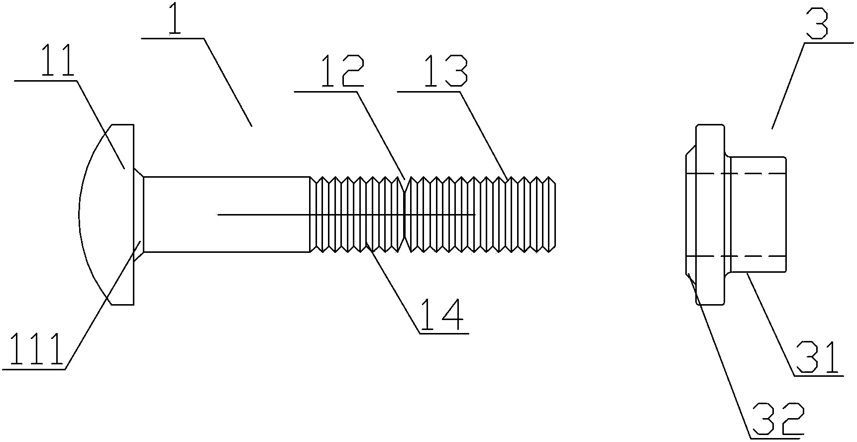
[0039] An anti-displacement riveting bolt provided by the present invention includes a metal riveting rod 1, the inner end of the metal riveting rod is provided with a convex head 11, the outer side of the metal riveting rod 1 has a breaking part 12, and there are tools and tools outside the breaking part. The connected connecting section 13; the rivet bolt is also provided with a fastening sleeve 3, and the fastening sleeve 3 is located on the outer side of the connected piece 100. The connected piece 100 can be a plate, and the metal rivet The rod 1 has an anti-loosening riveting section 14 corresponding to the fastening sleeve 3, and the anti-loosening riveting section 14 is made with anti-loosening, such as concave, convex, ring, annular groove, etc., so that the anti-loosening is fastened The segment 14 has an uneven surface. The inner hole of the fastening sleeve 3 is slightly larger than the anti-r...

Embodiment 2

[0057] Example 2, refer to figure 2 .

[0058] This embodiment is basically the same as Embodiment 1, except that the convex rings 32 and 111 of Embodiment 1 are changed to the plurality of protrusions 32 and 111 arranged in the circumferential direction of this embodiment, and their shapes can be dot-shaped or block-shaped. , the function of the protrusion 32 in this embodiment is the same as that of the convex ring 32 in the first embodiment, and the function of the protrusion 111 in this embodiment is the same as that of the convex ring 111 in the first embodiment. There is a tooth pattern matching the tooth pattern in the hole wall of the hole for the metal riveting rod on the connected piece and the hole wall of the hole for the metal riveting rod on the part to be connected with the connecting piece. The tooth pattern that matches the internal tooth pattern. figure 2 , unless otherwise stated, other figure 1 The reference numerals with the same reference numerals re...

Embodiment 3

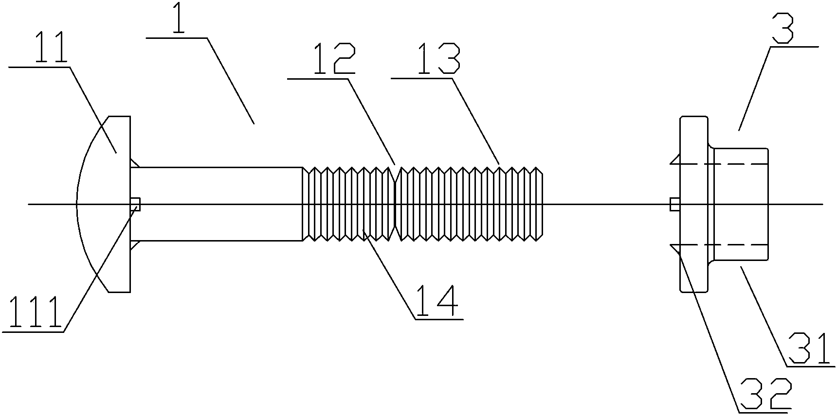
[0059] Example 3, refer to image 3 , 4 .

[0060] In addition, this embodiment is basically the same as Embodiments 1 and 2, except that the convex ring or protrusion 32 is no longer provided, but the following structure is retained:

[0061] The front end surface of the fastening sleeve also has a concave-convex positioning configuration 33 that matches the outer surface of the connected piece. The positioning configuration produces a non-slip fit on the outer surface of the connected piece and the front end surface of the fastening sleeve to further prevent the connected piece from loosening and displace. Anti-slip configuration; the hole through which the metal riveting rod passes through the connected piece is a long hole or a round hole or a long groove, so that the system applying the present invention has the function of compensating for position changes or errors.

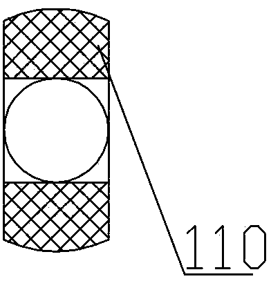
[0062]The rear end surface of the male head also has a concave-convex positioning configuration 110 ...


PUM


Abstract

The invention provides a drifting-proof rivet bolt and a connecting structure of a building appendage. The rivet bolt is provided with a fixing sleeve and a metal rivet rod which is provided with a dropping-proof riveting segment corresponding to the fixing sleeve; under the action of a tool, the fixing sleeve is pressed against a connecting part, an inner hole of the fixing sleeve is tightened and wrapped outside the dropping-proof riveting segment, and a bumpy inner-hole surface matching with dropping-preventing lines on the surface of the dropping-proof riveting segment is formed simultaneously; permanent connection is formed and welding is omitted. A slide-proof positioning structure is arranged on the fixing sleeve and/or a raised-head side. According to the drifting-proof rivet bolt, permanent and firm connection and dropping prevention can be realized, connecting strength is improved greatly, the requirement on shock absorption is met, and labor force and cost can be saved. Drifting-preventing and positioning relationships between the fixing sleeve and the building appendage, and the metal rivet rod and parts connected with the connecting part are brought in, structure is simple, using effect is good, and strength and firmness of connecting and mounting can be improved greatly. The invention further provides a solution for fire proofing and heat resisting of the rivet bolt, and the drifting-proof rivet bolt is adaptable to various fire resisting areas.

Description

technical field [0001] The invention relates to an anti-displacement riveting bolt and a connecting structure, which is mainly suitable for the riveting of various building curtain walls and various products with high requirements on earthquake resistance and precision. It is especially suitable for the curtain wall of building outer protective structure with high requirements for anti-vibration, anti-slip and anti-loosening. Background technique [0002] At present, the anchor bolts used in the curtain wall of the building envelope are affected by hundreds of thousands of wind waves every year and external forces such as thermal expansion and contraction, which will lead to the loosening of the anchors and the sagging of the gap between the connecting holes, causing accidents. Therefore, in order to prevent the bolts from loosening and the gap between the connecting holes from sagging, the national code stipulates that the screws, washers, nuts and connecting anchor plates ...

Claims


Application Information

Patent Timeline
IPC IPC(8): F16B19/04F16B39/284F16B41/00E04B1/38
Inventor 张清华徐洁媛徐跃华曾娜陈丽娟朱艺章蓓杜奕奎
Owner 浙江斯泰新材料科技股份有限公司
Why Eureka
Try Eureka