Eureka AIR delivers breakthrough ideas for toughest innovation challenges, trusted by R&D personnel around the world.

Installation method of diesel engine provided with shock absorbers on base

An installation method and shock absorber technology, which are applied in the field of mechanical installation engineering, can solve problems such as large mechanical vibration and mechanical noise, low power output efficiency, and inflexible installation, and achieve high power output efficiency, improved production efficiency, and low installation volume. small effect

Active Publication Date: 2013-11-27
WUCHANG SHIPBUILDING IND
View PDF4 Cites 5 Cited by
  • Summary
  • Abstract
  • Description
  • Claims
  • Application Information

AI Technical Summary

Problems solved by technology

[0002] The application range of the existing diesel engine installation technology is mainly used for the direct rigid connection installation method between the diesel engine and the base. Mechanical vibration and mechanical noise, poor comfort
The existing diesel engine installation technology is limited by the way of power output. On the one hand, when the power is directly output under rigid conditions through rigid shaft connections and other connectors, the alignment requirements during installation are relatively high; on the other hand, the power is indirectly output through belt or chain connections. , low power output efficiency during operation
However, in the existing shock absorbing installation technology, the diesel engine and the gearbox must first be assembled together through an installation platform, and then a shock absorber is installed under the platform, resulting in large volume, heavy weight, and inflexible installation.

Method used


Image

  • Installation method of diesel engine provided with shock absorbers on base
  • Installation method of diesel engine provided with shock absorbers on base

Examples


Embodiment Construction

[0021] The present invention will be described in further detail below in conjunction with the accompanying drawings and embodiments.

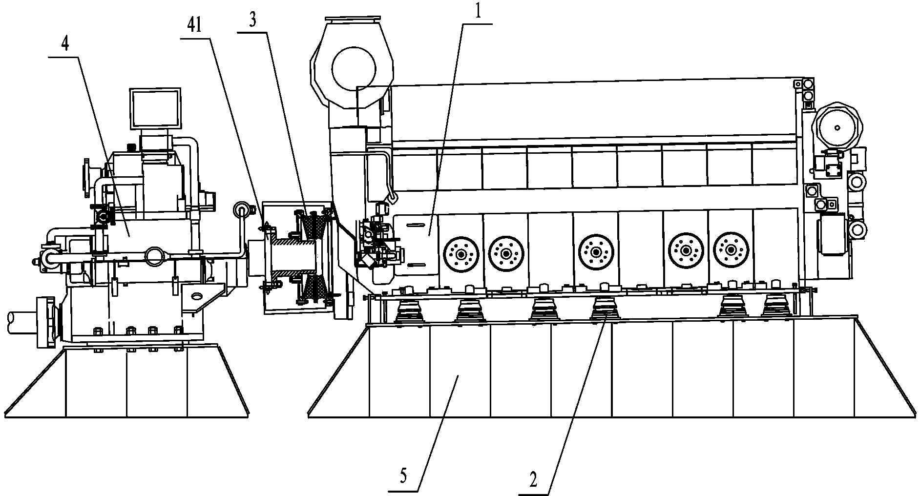
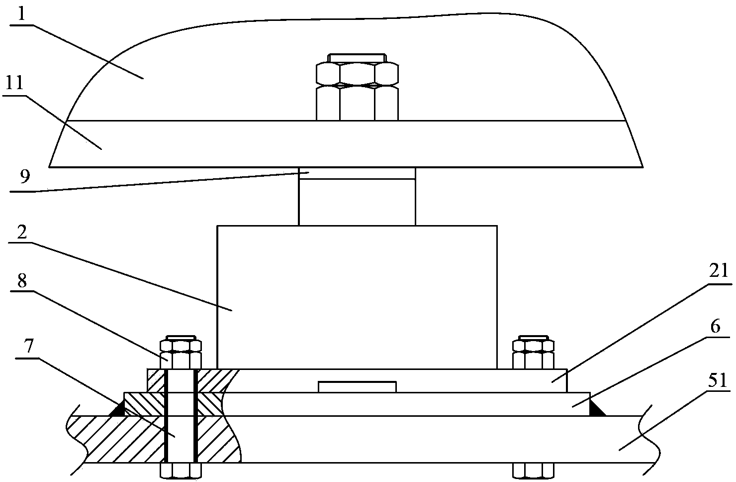
[0022] Such as figure 1 and figure 2 As shown, the diesel engine 1 with a plurality of shock absorbers 2 on the base of the present invention is arranged on the base 5, and a shock absorber backing plate 6 is arranged between the base 5 and each shock absorber 2, and the diesel engine 1 passes through the shaft coupling The coupling 3 is connected to a gearbox 4, one end of the coupling 3 is connected to the output end of the diesel engine 1, and the other end is connected to the input flange 41 of the gearbox 4.

[0023] During the implementation of the present invention, conditions need to be met before installation:

[0024] (1) The power output equipment of the diesel engine 1 has been installed, such as the gearbox 4, etc. have been installed.

[0025] (2) The welding installation and pyrotechnic calibration of the structure near the ...


PUM

PropertyMeasurementUnit
Thicknessaaaaaaaaaa

Abstract

The invention relates to an installation method of a diesel engine provided with shock absorbers on a base and relates to the field of mechanical installation projects. The installation method includes the steps of S1, mounting the base, whose top includes a base support face; S2, calculating compression of each shock absorber, measuring the central height between the support face of the base and the lower surface of the base of the diesel engine, and producing an absorber base plate below each shock absorber; S3, connecting multiple shock absorbers to the lower surface of the base of the diesel engine, placing multiple absorber base plates on a support top plate, and seating the diesel engine on the absorber base plates; S4, grinding machining allowance of each absorber base plate until curvature and offset of the diesel engine are satisfactory to the centering standard, and fixedly welding each absorber base plate to the base support face; S5, fixedly connecting the base of each shock absorber, the absorber base plates and the base support face through bolts and nuts. The method has the advantages that the centering demand is low, power output efficiency is high, the size is small, the weight is light and installation is flexible.

Description

technical field [0001] The invention relates to the field of mechanical installation engineering, in particular to a method for installing a diesel engine with a base provided with a shock absorber. Background technique [0002] The application range of the existing diesel engine installation technology is mainly used for the direct rigid connection installation method between the diesel engine and the base. Mechanical vibration and mechanical noise, poor comfort. The existing diesel engine installation technology is limited by the way of power output. On the one hand, when the power is directly output under rigid conditions through rigid shaft connections and other connectors, the alignment requirements during installation are relatively high; on the other hand, the power is indirectly output through belt or chain connections. , the power output efficiency is low during operation. However, in the existing shock absorbing installation technology, the diesel engine and the ...

Claims


Application Information

Patent Timeline
IPC IPC(8): F16F15/02
Inventor 许克文秦启虎
Owner WUCHANG SHIPBUILDING IND
Why Eureka
Eureka Blog
Learn More