
LED lamp for improving lighting effect and reducing light attenuation

A technology of LED lamps and LED chips, which is applied in the field of LED lamps, can solve the problems of attenuation, lack of attention, and the inability to effectively improve the efficiency and reliability of LED street lamps, so as to avoid direct contact and solve the problem of LED device color. Drift and brightness attenuation problems, the effect of improving the life of the whole lamp and the maintenance rate of luminous flux

Inactive Publication Date: 2013-11-27
NANTONG YAPU LIGHTING ELECTRICAL APPLIANCE MFG
View PDF14 Cites 0 Cited by
  • Summary
  • Abstract
  • Description
  • Claims
  • Application Information

AI Technical Summary

Problems solved by technology

At present, the packaging level of mainstream LED integrated forms in China, the main technical parameters that can be mass-produced are basically between 100-110LM / W, and according to the current product packaging structure and packaging process, the 2000-hour light decay level is basically 10% About, after the 2000-hour lighting life is over, in addition to the 10% attenuation of the light decay, there is another key indicator, the color will change, but domestic manufacturers have not paid enough attention to this point, based on the LED light source. The core components of LED street lamps, if the above two points are not improved, the overall efficiency and reliability of LED street lamps cannot be effectively improved

Method used


Image

  • LED lamp for improving lighting effect and reducing light attenuation
  • LED lamp for improving lighting effect and reducing light attenuation
  • LED lamp for improving lighting effect and reducing light attenuation

Examples


Embodiment Construction

[0016] In order to deepen the understanding of the present invention, the present invention will be further described below in conjunction with the embodiments and accompanying drawings. The embodiments are only used to explain the present invention and do not constitute a limitation to the protection scope of the present invention.

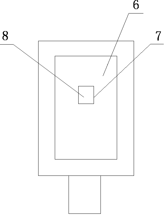
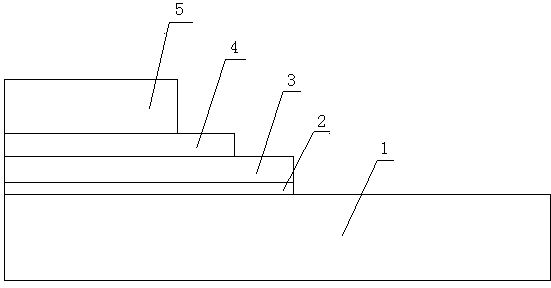
[0017] Such as figure 1 , figure 2 and image 3 As shown, an LED lamp with improved light efficiency and reduced light decay of the present invention includes an LED lamp body 6, a groove 7 sunken downward is opened in the middle of the LED lamp body 6, and an LED light source 8 is installed in the groove 7, and the LED light source 8 includes an LED chip and a metal substrate 1, the LED chip is set on the upper surface of the metal substrate 1, an insulating layer 2 is laid on the metal substrate 1, a circuit layer 3 is arranged on the insulating layer 2, and the positive and negative leads of the metal substrate 1 are welded On the line laye...


PUM


Abstract

The invention discloses an LED lamp for improving the lighting effect and reducing the light attenuation. The LED lamp comprises an LED lamp body, a downwards-concave groove is formed in the middle of the LED lamp body, an LED light source is installed in the groove and comprises an LED chip and a metal substrate, the LED chip is arranged on the upper surface of the metal substrate, an insulation layer is paved on the metal substrate, a circuit layer is arranged on the insulation layer, a packaging glue limiting layer made of insulation materials is paved on the circuit layer, a fluorescence glue limiting layer made of insulation materials is paved on the packaging glue limiting layer, packaging glue is poured into the packaging glue limiting layer, and fluorescence glue is poured into the fluorescence glue limiting layer. The LED lamp for improving the lighting effect and reducing the light attenuation has the advantages that the direct contact between the fluorescence glue and a wafer is avoided, transfer efficiency of fluorescent powder is reduced due to the heating effect to the fluorescent powder by heat emitted when the wafer is lighted, the radiating efficiency of the whole LED streetlamp is improved, accordingly, the service life of the whole LED lamp is prolonged, and the retention rate of light quantity is improved.

Description

technical field [0001] The invention relates to an LED lamp, in particular to an LED lamp with improved light efficiency and reduced light decay. Background technique [0002] The current research direction in China mainly focuses on the improvement of luminous efficiency, and some foreign and domestic companies have proposed that the luminous efficiency should be increased to 150lm / W by 2015, but they have not elaborated on the detailed plan. There is a goal to solve the problem of LED color drift other than light efficiency. Our company is now setting the goal to solve the problem of color drift and light effect at the same time according to the higher standards of the peers, so as to enhance product competitiveness. At present, the packaging level of mainstream LED integrated forms in China, the main technical parameters that can be mass-produced are basically between 100-110LM / W, and according to the current product packaging structure and packaging process, the 2000-hou...

Claims


Application Information

Patent Timeline
Patent Type & Authority Applications(China)
IPC IPC(8): F21S2/00F21V17/00F21V19/00H01L33/48H01L33/54H01L33/50H01L33/64F21Y101/02
Inventor 周洁
Owner NANTONG YAPU LIGHTING ELECTRICAL APPLIANCE MFG
Learn More