[0036] It should be understood that the specific embodiments described herein are only used to explain the present invention, but not to limit the present invention.
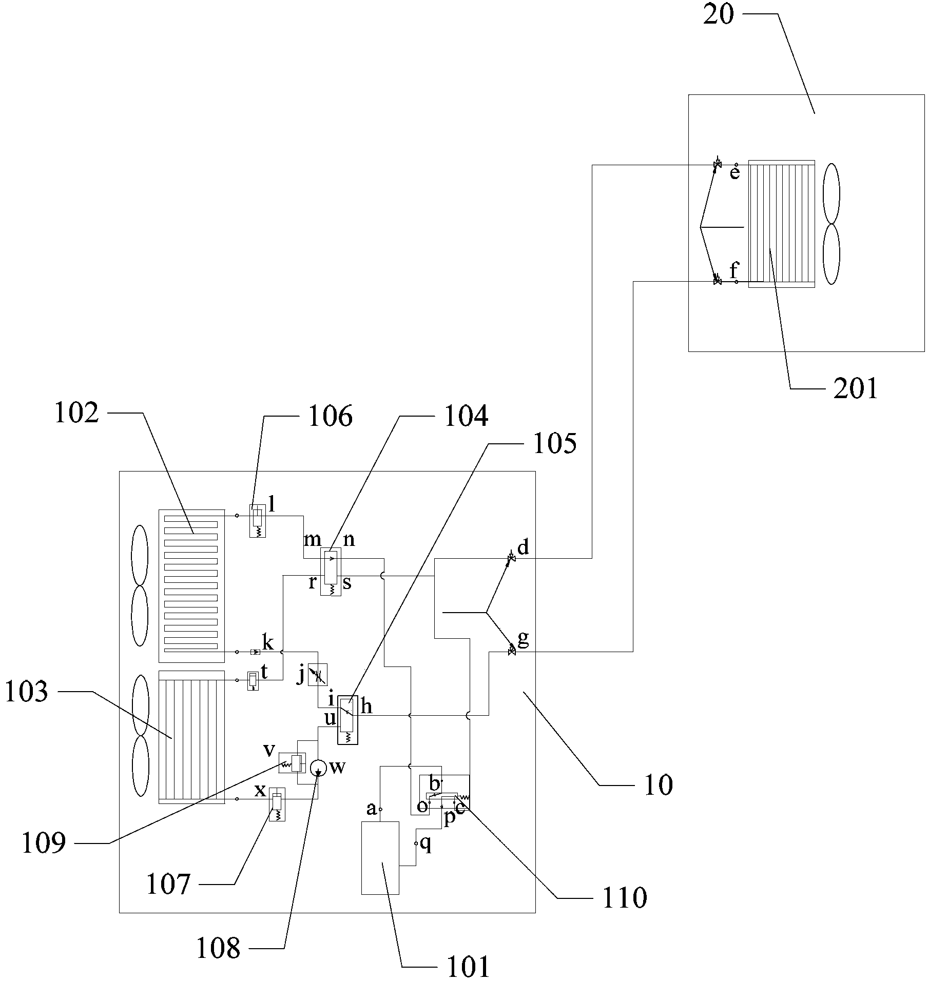
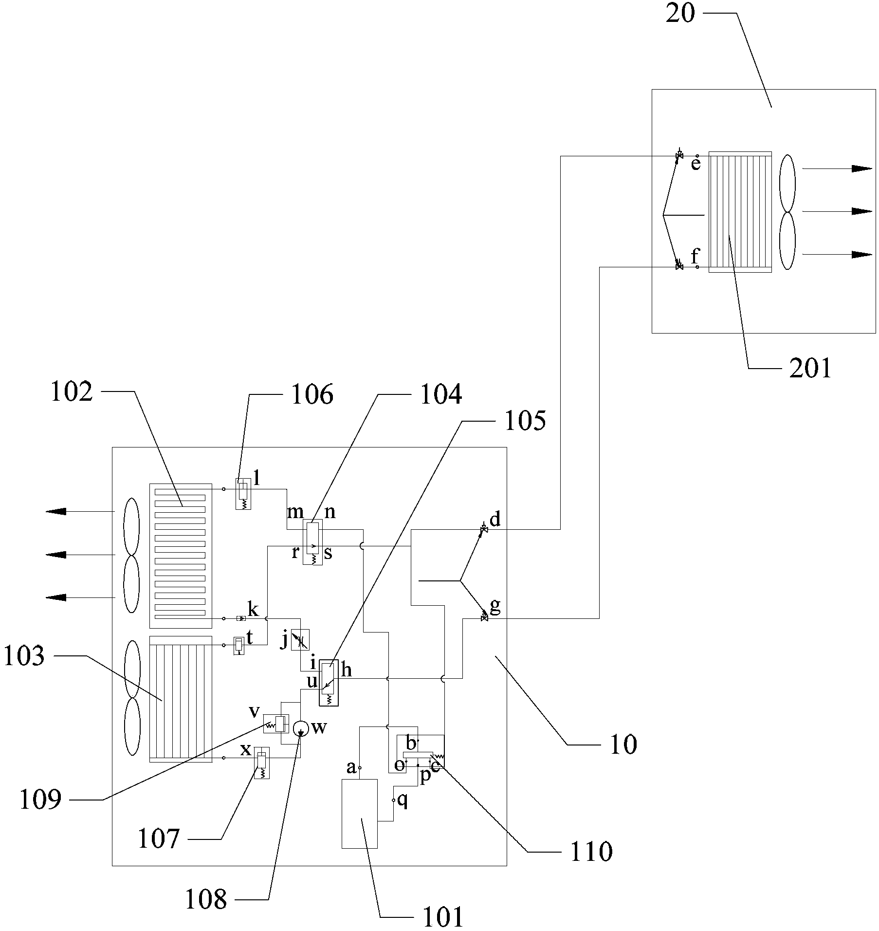
[0037] The invention provides a refrigeration system, which is used for cooling equipment in a computer room of a communication base station. The air conditioning refrigeration system and the heat pipe refrigeration system are combined into a whole refrigeration system, and respectively form the air conditioning mode loop and the heat pipe mode loop. Different cooling modes are used for cooling under different outdoor ambient temperatures, and when switching to a cooling mode, all the refrigerant in the system in the current cooling mode is recovered.
[0038] Reference Figure 1 to Figure 4 , figure 1 It is a schematic structural diagram of the air conditioning refrigeration mode in the first embodiment of the refrigeration system of the present invention; figure 2 It is a schematic structural diagram of the air conditioning refrigerant recovery mode in the first embodiment of the refrigeration system of the present invention; image 3 It is a schematic structural diagram of the heat pipe cooling mode in the first embodiment of the refrigeration system of the present invention; Figure 4 It is a schematic structural diagram of the heat pipe refrigerant recovery mode in the first embodiment of the refrigeration system of the present invention.
[0039] The refrigeration system provided in this embodiment includes an indoor unit 10 and an outdoor unit 20. The indoor unit 10 includes a compressor 101, a first indoor heat exchanger 102 and a second indoor heat exchanger 103; the outdoor unit 20 includes an outdoor heat exchanger 201; in this embodiment, the first indoor heat exchanger 102, the second indoor heat exchanger 103, and the outdoor heat exchanger 201 can all be tube-fin heat exchangers or parallel flow heat exchangers; the first indoor heat exchanger 102. The second indoor heat exchanger 103 and the outdoor heat exchanger 201 are connected through a connecting pipe, and a first stop valve and a second stop valve are arranged between the connecting pipes, wherein:
[0040] The exhaust port a of the compressor 101 is connected to one end of the outdoor heat exchanger 201, the other end of the outdoor heat exchanger 201 is connected to one end of the first indoor heat exchanger 102, and the other end of the first indoor heat exchanger 102 is connected to the compressor The air return port q of 101 forms a circuit in the air-conditioning mode. At this time, the cooling mode is the air-conditioning mode. In this embodiment, the air-conditioning mode includes an air-conditioning refrigeration mode and an air-conditioning refrigerant recovery mode;
[0041] The second indoor heat exchanger 103 can be arranged below the first indoor heat exchanger 102, and its height is lower than that of the outdoor heat exchanger 201 to ensure that the height difference between the outdoor unit and the indoor and outdoor units can be effectively utilized in the heat pipe cooling mode. Cooling capacity. One end of the second indoor heat exchanger 103 is connected to one end of the outdoor heat exchanger 201, and the other end of the outdoor heat exchanger 201 is connected to the other end of the second indoor heat exchanger 103 to form a loop in the heat pipe mode. At this time, the cooling mode It is a heat pipe mode. In this embodiment, the heat pipe mode includes a heat pipe cooling mode and a heat pipe refrigerant recovery mode.
[0042] When the outdoor ambient temperature is higher than the preset temperature value, the air-conditioning mode is used for cooling, so as to give play to the advantages and efficiency of the air-conditioning cooling mode. In this embodiment, the preset temperature value can be customized to ensure that the advantages and efficiency of the air conditioning refrigeration mode are fully utilized in an appropriately high external temperature environment. When the outdoor environment temperature is lower than the preset temperature value, the cooling efficiency of the air conditioning mode is lower, and its advantages are not obvious, so the heat pipe mode is used for cooling.
[0043] In the above embodiment, the indoor unit 10 further includes:
[0044] The first electromagnetic reversing valve 104 is connected between the first indoor heat exchanger 102 and the return air port q of the compressor 101, and between the second indoor heat exchanger 103 and the outdoor heat exchanger 201; in this embodiment, the first An electromagnetic reversing valve 104 can adopt a two-position four-way electromagnetic reversing valve, which includes four nozzles m, n, r, and s;
[0045] The second electromagnetic reversing valve 105 is connected between the first indoor heat exchanger 102 and the outdoor heat exchanger 201, and between the second indoor heat exchanger 103 and the outdoor heat exchanger 201; in this embodiment, the second electromagnetic The reversing valve 104 may adopt a two-position three-way electromagnetic reversing valve, which includes three nozzles i, u, and h.
[0046] In this embodiment, a one-way valve k and a throttle valve j are also connected between the first heat exchanger 102 and the second electromagnetic directional valve 105; the second heat exchanger 102 and the first electromagnetic directional valve 104 is also connected to a fourth electromagnetic directional valve t, and the fourth electromagnetic directional valve t may be a two-position two-way electromagnetic directional valve.
[0047] When the refrigeration system is switched between cooling modes, the flow of refrigerant is switched by the first electromagnetic reversing valve 104 and the second electromagnetic reversing valve 105. When the refrigeration system is in air conditioning mode, the nozzle m of the first electromagnetic reversing valve 104 and The pipe port n is connected, and the pipe port i of the second electromagnetic reversing valve 105 is connected to the pipe port h; when the refrigeration system is in the heat pipe mode, the pipe port r and the pipe port s of the first solenoid reversing valve 104 are connected, and the second solenoid The nozzle u and the nozzle h of the reversing valve 105 communicate.
[0048] In the above embodiment, a first pressure controller 106 is connected between the first heat exchanger 102 and the first electromagnetic reversing valve 104. The first pressure controller 106 is denoted by l, and one end of the first pressure controller 106 exchanges with the first heat exchanger. The other end is connected to the nozzle m of the first electromagnetic reversing valve 104; a second pressure controller 107 is connected between the second heat exchanger 103 and the second electromagnetic reversing valve 105, and the second pressure The controller 107 is represented by x, one end of which is connected to the second heat exchanger 103, and the other end is connected to the nozzle u of the second electromagnetic reversing valve 105.
[0049] When the refrigerant in the refrigeration system is recovered, since the refrigerant generates pressure in the circuit in the corresponding mode, the pressure of the refrigerant is detected by the first pressure controller 106 and the second pressure controller 107, and the pressure of the refrigerant reaches the preset value. When the set recovery pressure value is set to disconnect. In the air-conditioning refrigerant recovery mode and the heat pipe refrigerant recovery mode, the first recovery pressure value and the second recovery pressure value used to determine whether the refrigerant is compressed to the corresponding heat exchanger in the two modes are respectively preset. In the air conditioning refrigerant recovery mode, when the pressure generated by the refrigerant reaches the first recovery pressure value, the first pressure controller 106 is turned off; in the heat pipe refrigerant recovery mode, when the pressure generated by the refrigerant reaches the second recovery pressure value, the first pressure controller 106 is turned off. The second pressure controller 107 is turned off.
[0050] In the above embodiment, the indoor unit 10 also includes a power pump 108 connected between the second pressure controller 107 and the second electromagnetic reversing valve 105. In this embodiment, the power pump 108 is represented by w; in the heat pipe refrigerant In the recovery mode, the power pump 108 starts to work to provide circulating power for the refrigeration system to recover the refrigerant; when the pressure generated by the refrigerant reaches the second recovery pressure value, the power pump 108 stops working.
[0051] In the above embodiment, the indoor unit 10 further includes an unloading valve 109 connected between the second pressure controller 107 and the second electromagnetic reversing valve 105. The unloading valve 109 is represented by v; when the refrigerant is in the power pump 108 When the pressure is too high, the unloading valve 109 works to release the pressure.
[0052] In the above embodiment, a third electromagnetic reversing valve is also connected between the exhaust port a of the compressor 101 and the outdoor heat exchanger 201, and the first indoor heat exchanger 102 and the air return port q of the compressor 101 110. When the refrigeration system switches between the air-conditioning refrigeration mode and the air-conditioning refrigerant recovery mode, the third electromagnetic reversing valve 110 switches the flow direction of the refrigerant. In this embodiment, the third electromagnetic reversing valve 110 may be a three-position four-way electromagnetic reversing valve, which includes four orifices o, b, c, and p, wherein the orifice b is connected to the exhaust port of the compressor 101 a is in communication, and the pipe port p is in communication with the return air port q of the compressor 101. When the refrigeration system is in the air-conditioning refrigeration mode, the pipe port b and the pipe port c of the third electromagnetic reversing valve 110 are connected, and the pipe port o and the pipe port p are connected; when the refrigeration system is in the air-conditioning refrigerant recovery mode, the third electromagnetic reversing valve The nozzle b of the valve 110 communicates with the nozzle o, and the nozzle c communicates with the nozzle p.
[0053] The following describes the working principles of the refrigeration system in four modes: air conditioning cooling mode, air conditioning refrigerant recovery mode, heat pipe cooling mode, and heat pipe refrigerant recovery mode:
[0054] 1. The refrigeration system is in the air conditioning refrigeration mode:
[0055] Such as figure 1 , figure 1 The schematic diagram of the structure of the refrigeration system in the air-conditioning refrigeration mode is shown. When the refrigeration system is in the air-conditioning refrigeration mode, the compressor 101, the first indoor heat exchanger 102, the indoor fan corresponding to the first indoor heat exchanger 102, the outdoor heat exchanger 201 and the outdoor fan work to achieve heat exchange; the fourth electromagnetic exchange The valve t is disconnected from the second pressure controller 107; in this cooling mode, the refrigerant flow direction is abcdefghijklmnopqa, and the heat pipe mode must be in the state where the heat pipe refrigerant recovery is complete. In the heat pipe cooling mode, the refrigerant in the system has been completely recovered to the first The second heat exchanger 103.
[0056] The refrigerant flowing out of the exhaust port a of the compressor 101 first flows to the nozzle b of the third electromagnetic reversing valve 110, and flows to the indoor heat exchanger and the outdoor heat exchanger through the pipe c of the third electromagnetic reversing valve 110 The pipe port d of the first shut-off valve between the connecting pipes flows into the outdoor heat exchanger 201 through the pipe port e of the second shut-off valve for heat exchange, and the refrigerant after heat exchange through the outdoor heat exchanger 201 passes through the second The nozzle f of the stop valve flows to the nozzle g of the first stop valve, and flows into the first heat exchanger 102 through the nozzle h and the nozzle i of the second electromagnetic directional valve 105, the throttle valve j and the one-way valve k For heat exchange, the refrigerant after the heat exchange by the first heat exchanger 102 flows through the first pressure controller 106 to the nozzle m of the first electromagnetic reversing valve 104, and flows out from the nozzle n, and finally passes through the third electromagnetic reversing The nozzle o and the nozzle p of the valve 110 flow to the air return port q of the compressor 101 to complete the cooling process in the air conditioning cooling mode.
[0057] Such as figure 2 , figure 2 The schematic diagram of the structure of the refrigeration system in the air conditioning refrigerant recovery mode is shown. When the refrigeration system is in the air conditioning refrigerant recovery mode, the compressor 101, the first indoor heat exchanger 102, the first indoor heat exchanger 102 and the outdoor heat exchanger 201 work; the indoor fan and outdoor fan corresponding to the first indoor heat exchanger 102 Stop working, the fourth electromagnetic reversing valve t and the second pressure controller 107 are disconnected; in this cooling mode, the refrigerant flow direction is kjihgfedcpqabonmlk.
[0058] Since the one-way valve k can only achieve one-way flow, the refrigerant in the first heat exchanger 102 cannot flow out through the one-way valve k. Therefore, when the refrigerant is recovered, the compressor 101 works to make the refrigerant flow from the one-way valve k. It starts to flow at the throttle valve j, the nozzle i and the nozzle h of the second solenoid directional valve 105, and the nozzle g of the first shut-off valve to flow to the nozzle f of the second shut-off valve and pass through the second shut-off valve. The nozzle e of the valve and the nozzle d of the first stop valve flow to the nozzle c and the nozzle p of the third electromagnetic directional valve 110, and flow into the compressor 101 through the return air port q of the compressor 101, and from the compressor 101 The refrigerant flowing out of the exhaust port a of the third electromagnetic reversing valve 110 flows to the pipe port n of the first electromagnetic reversing valve 104 through the pipe port b and the pipe port o of the third electromagnetic reversing valve 110, and passes through the pipe port of the first electromagnetic reversing valve 104 m and the first pressure controller 106 flow into the first heat exchanger 102. Similarly, due to the one-way nature of the one-way valve k, the refrigerant in the first heat exchanger 102 will not flow out through the one-way valve k. At this time, the first pressure controller 106 detects the pressure of the refrigerant in the current system. When the pressure of the refrigerant reaches the first recovery pressure value, the first pressure controller 106 is turned off, and the refrigerant in the refrigeration system in the air-conditioning refrigeration mode is completely removed. It is recycled to the first heat exchanger 102.
[0059] Such as image 3 , image 3 The schematic diagram of the structure of the refrigeration system in the heat pipe cooling mode is shown. When the refrigeration system is in the heat pipe cooling mode, the second indoor heat exchanger 103, the indoor fan corresponding to the second indoor heat exchanger 103, the outdoor heat exchanger 201 and the outdoor fan work, and the power pump 108 provides power for the system; the compressor 101 does not Work, the first pressure controller 106 is disconnected, and the spool of the third solenoid directional valve 110 is in the position where the four pipe ports p, c, b, and o are all disconnected; in this cooling mode, the refrigerant flow direction is defghuwxtrsd, and the air-conditioning mode must be in a state where the air-conditioning refrigerant has been recovered. In the air-conditioning refrigeration mode, the refrigerant in the system has been completely recovered to the first heat exchanger 102.
[0060] After the refrigerant exchanges heat in the second heat exchanger 103, it flows from the nozzle d of the first shut-off valve through the nozzle e of the second shut-off valve into the outdoor heat exchanger 201 for heat exchange, and the refrigerant after heat exchange is shut off from the second The nozzle f of the valve flows from high to low to the nozzle g of the first shut-off valve, and flows into the second solenoid valve 105 through the nozzle h and the nozzle u, the power pump 108 and the second pressure controller 107. In the heat exchanger 103, the refrigerant after the heat exchange in the second heat exchanger 103 flows out from the fourth electromagnetic directional valve t, passes through the nozzle r and the nozzle s of the first electromagnetic directional valve 104, and flows to the first stop valve The nozzle d of, finally completes the cooling process in the heat pipe cooling mode.
[0061] Such as Figure 4 , Figure 4 Shows the structure diagram of the refrigeration system in the heat pipe refrigerant recovery mode. The refrigeration system is in the heat pipe refrigerant recovery mode, the second indoor heat exchanger 103 and outdoor heat exchanger 201 work, the indoor fan and outdoor fan corresponding to the second indoor heat exchanger 103 stop working, and the power pump 108 provides power for heat pipe refrigerant recovery ; The compressor 101 is not working, the first pressure controller 106 is disconnected, and the spool of the third solenoid directional valve 110 is in a position where the four pipe ports p, c, b, and o are all disconnected; in this cooling mode When the refrigerant flows in trsdefghuwxt.
[0062] When the refrigerant is recovered, the power pump 108 works, so that the refrigerant in the refrigeration system starts to flow from the fourth electromagnetic reversing valve t, passing through the nozzle r and the nozzle s of the first electromagnetic reversing valve 104 to the first stop The nozzle d of the valve flows through the nozzle e and the nozzle f of the second stop valve and the nozzle g of the first stop valve to the nozzle h of the second electromagnetic reversing valve 105, and then passes through the second electromagnetic reversing valve. The nozzle u of the valve 105, the power pump 108 and the second pressure controller 107 finally flow into the second heat exchanger 103. At this time, the pressure of the refrigerant in the current system is detected by the second pressure controller 107. When the pressure of the refrigerant reaches the second recovery pressure value, the second pressure controller 107 is turned off, and the refrigerant in the refrigeration system in the air-conditioning refrigeration mode is all It is recovered to the second heat exchanger 103; if the pressure of the refrigerant at the power pump 108 is too high, the unloading valve 109 works to release the pressure and keep the system stable.
[0063] In this embodiment, the air-conditioning refrigeration system and the heat pipe refrigeration system are combined into an integral refrigeration system, and the circuit of the air conditioning mode and the circuit of the heat pipe mode are formed respectively. The refrigeration system includes an indoor unit 10 and an outdoor unit 20. The indoor unit 10 includes a compressor 101, a first indoor heat exchanger 102 and a second indoor heat exchanger 103. The outdoor unit 20 includes an outdoor heat exchanger 201; a compressor 101, The first indoor heat exchanger 102 and the outdoor heat exchanger 201 form a loop in the air conditioning mode; the second indoor heat exchanger 103 and the outdoor heat exchanger 201 form a loop in the heat pipe mode. Use different cooling modes to cool under different outdoor ambient temperatures, and when switching to another cooling mode, all the refrigerant in the system under the current cooling mode is recovered, thereby meeting the cooling requirements under different working conditions and improving Improved refrigeration efficiency and reduced equipment procurement costs.
[0064] Reference Figure 5 , Figure 5 It is a schematic structural diagram of the second embodiment of the refrigeration system of the present invention.
[0065] On the basis of the first embodiment of the refrigeration system of the present invention, the indoor unit 10 of the refrigeration system further includes a humidification device, which is connected to the power pump 108. When the refrigeration system is in the heat pipe cooling mode, the power pump 108 is the humidification device Provide power to humidify the equipment in the communication base station room to maintain the humidity in the room. In this embodiment, the humidification device includes a water receiving tank 111 arranged below the second heat exchanger 103 and a nozzle 112 connected to the water receiving tank 111. When the refrigeration system is in the heat pipe cooling mode, the refrigerant is in the second heat exchanger. The condensed water generated after heat exchange in 103 flows into the water receiving tank 111, and the condensed water can be used as a water source for humidifying the nozzle 112.
[0066] In the indoor unit section of the heat pipe mode, a humidification device is added to use the condensed water generated in the second heat exchanger 103 during cooling as a water source for humidification. While ensuring the reuse of resources, the equipment room of the communication base station can be kept at a certain level. Humidity, so as to prevent the equipment from generating static electricity.
[0067] The invention also provides a refrigeration method for the refrigeration system.
[0068] Reference Image 6 , Image 6 It is a schematic flow chart of an embodiment of a refrigeration method for a refrigeration system of the present invention.
[0069] The refrigeration method of the refrigeration system provided in this embodiment includes:
[0070] Step S10, select the corresponding cooling mode according to the outdoor ambient temperature, and control the corresponding indoor heat exchanger and indoor fan to work;
[0071] In this embodiment, the refrigeration system includes an indoor unit and an outdoor unit. The indoor unit includes a compressor, a first indoor heat exchanger and a second indoor heat exchanger; the outdoor unit includes an outdoor heat exchanger; a first indoor heat exchanger, The second indoor heat exchanger and the outdoor heat exchanger are connected through a connecting pipe, and a first stop valve and a second stop valve are arranged between the connecting pipes, wherein:
[0072] The exhaust port of the compressor is connected to one end of the outdoor heat exchanger, the other end of the outdoor heat exchanger is connected to one end of the first indoor heat exchanger, and the other end of the first indoor heat exchanger is connected to the air return port of the compressor to form an air conditioner In the circuit in the mode, the cooling mode is the air-conditioning mode at this time. In this embodiment, the air-conditioning mode includes the air-conditioning cooling mode and the air-conditioning refrigerant recovery mode;
[0073] The second indoor heat exchanger is arranged below the first indoor heat exchanger, and its height is lower than that of the outdoor heat exchanger to ensure that the height difference between the outdoor unit and the indoor and outdoor units can be effectively used to obtain cooling capacity in the heat pipe cooling mode. One end of the second indoor heat exchanger is connected to one end of the outdoor heat exchanger, and the other end of the outdoor heat exchanger is connected to the other end of the second indoor heat exchanger to form a loop in the heat pipe mode. At this time, the cooling mode is the heat pipe mode. In this embodiment, the heat pipe mode includes a heat pipe cooling mode and a heat pipe refrigerant recovery mode.
[0074] When the equipment in the communication base station computer room is cooled, the corresponding cooling mode is selected according to the current outdoor ambient temperature, and the corresponding indoor heat exchanger and indoor fan are controlled to work.
[0075] In this embodiment, step S10 specifically includes:
[0076] When the outdoor environment temperature is greater than the preset temperature value, the air conditioning mode is selected for cooling, and the first indoor heat exchanger and the first indoor fan corresponding to the first indoor heat exchanger are controlled to work;
[0077] When the outdoor ambient temperature is less than or equal to the preset temperature value, the heat pipe mode is selected for cooling, and the second indoor heat exchanger and the second indoor fan corresponding to the second indoor heat exchanger are controlled to work.
[0078] When the current outdoor ambient temperature is higher than the preset temperature value, select the air conditioning mode for cooling, that is, control the first indoor heat exchanger and the first indoor fan corresponding to the first indoor heat exchanger to work, and at the same time, control the outdoor heat exchange The air conditioner and outdoor fan work to take advantage of the advantages and efficiency of the air conditioning cooling mode; when the outdoor ambient temperature is lower than the preset temperature value, the cooling efficiency of the air conditioning mode is lower, and its advantages are not obvious, so choose the heat pipe mode Perform cooling, control the operation of the second indoor heat exchanger and the second indoor fan corresponding to the second indoor heat exchanger, and at the same time control the operation of the outdoor heat exchanger and the outdoor fan. In this embodiment, the preset temperature value can be customized to ensure that the advantages and efficiency of the air-conditioning refrigeration mode are fully utilized in an appropriately high external temperature environment.
[0079] Step S20, when switching the cooling mode, switch to the refrigerant recovery mode in the current cooling mode, and recover all the refrigerant in the circuit of the current cooling mode;
[0080] When switching from the current cooling mode to another cooling mode, first switch to the refrigerant recovery mode in the current cooling mode, and recover all the refrigerant in the circuit of the current cooling mode. If the current cooling mode is air-conditioning mode, when switching to heat pipe mode, first switch from air-conditioning cooling mode to air-conditioning refrigerant recovery mode, and recover all the refrigerant in the refrigeration system in air-conditioning cooling mode to the first heat exchanger; such as current cooling When the mode is the heat pipe mode, when switching to the air conditioning mode, first switch from the heat pipe cooling mode to the heat pipe refrigerant recovery mode, and recover all the refrigerant in the refrigeration system in the heat pipe cooling mode to the second heat exchanger.
[0081] Step S30, controlling the operation of the switched indoor heat exchanger and indoor fan, and controlling the corresponding electromagnetic reversing valve to switch the direction of refrigerant flow.
[0082] After switching to the refrigerant recovery mode in the current cooling mode, the corresponding indoor heat exchanger and indoor fan after the switching are controlled to work, and the corresponding electromagnetic reversing valve is controlled to switch the direction of the refrigerant, thereby switching the cooling mode.
[0083] In this embodiment, step S30 specifically includes:
[0084] If the current cooling mode is the air conditioning mode, when the cooling mode is switched, the second indoor heat exchanger and the second indoor fan are controlled to work, the first electromagnetic reversing valve and the second electromagnetic reversing valve are reversing, and the refrigerant flow direction is switched;
[0085] If the current cooling mode is the heat pipe mode, when the cooling mode is switched, the first indoor heat exchanger and the first indoor fan are controlled to work, the first electromagnetic reversing valve and the second electromagnetic reversing valve are controlled to switch directions, and the refrigerant flow direction is switched.
[0086] If the current cooling mode is air-conditioning mode, when switching to heat pipe mode, after switching from air-conditioning cooling mode to air-conditioning refrigerant recovery mode, control the operation of the second indoor heat exchanger and the second indoor fan, outdoor heat exchanger and outdoor fan At the same time, it controls the reversal of the first electromagnetic reversing valve and the second electromagnetic reversing valve, switching the flow of refrigerant, and switching the air conditioning mode to heat pipe mode for cooling; if the current cooling mode is heat pipe mode, when switching to air conditioning mode After switching from the heat pipe cooling mode to the heat pipe refrigerant recovery mode, control the first indoor heat exchanger and the first indoor fan to work, the outdoor heat exchanger and the outdoor fan to work, and at the same time, control the first electromagnetic reversing valve and the second The electromagnetic reversing valve switches the direction of the refrigerant, and switches the heat pipe mode to the air conditioning mode for cooling.
[0087] The above are only the preferred embodiments of the present invention, and do not limit the scope of the present invention. Any equivalent structure or equivalent process transformation made by using the content of the description and drawings of the present invention, or directly or indirectly applied to other related The technical field is similarly included in the scope of patent protection of the present invention.