
Automatic identifying method of rotor system shaft center track precessional motion direction

A technology of axis trajectory and automatic recognition, which is applied in the direction of indicating/recording actions, measuring devices, instruments, etc., can solve problems such as low efficiency and complex recognition algorithms, and achieve the effect of strong versatility

Inactive Publication Date: 2013-11-27
NORTH CHINA ELECTRIC POWER UNIV (BAODING)
View PDF3 Cites 12 Cited by
  • Summary
  • Abstract
  • Description
  • Claims
  • Application Information

AI Technical Summary

Problems solved by technology

[0004] Aiming at the problem that the existing axis track identification method mentioned in the background technology can only identify the precession direction of some areas of the axis track when identifying complex axis tracks, and the recognition algorithm is complicated and inefficient, the present invention proposes A method for automatic recognition of the precession direction of the axis track of the rotor system

Method used


Image

  • Automatic identifying method of rotor system shaft center track precessional motion direction
  • Automatic identifying method of rotor system shaft center track precessional motion direction
  • Automatic identifying method of rotor system shaft center track precessional motion direction

Examples


Embodiment Construction

[0022] The preferred embodiments will be described in detail below in conjunction with the accompanying drawings. It should be emphasized that the following description is only exemplary and not intended to limit the scope of the invention and its application.

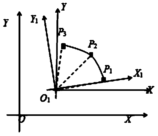
[0023] figure 1 It is a schematic diagram of an arc provided by the present invention. figure 1 Medium, P 1 ,P 2 ,P 3 are three consecutive points on the trajectory of the rotor purification axis, and their coordinates are (x 1 ,y 1 ), (x 2 ,y 2 ), (x 3 ,y 3 );O 1 is the center of an arc determined by these three consecutive points; XO 1 Y is the original coordinate system XOY and the coordinate system after translation is; X 1 o 1 Y 1 for XO 1 Y coordinate system around point O 1 The new coordinate system obtained by rotating counterclockwise.

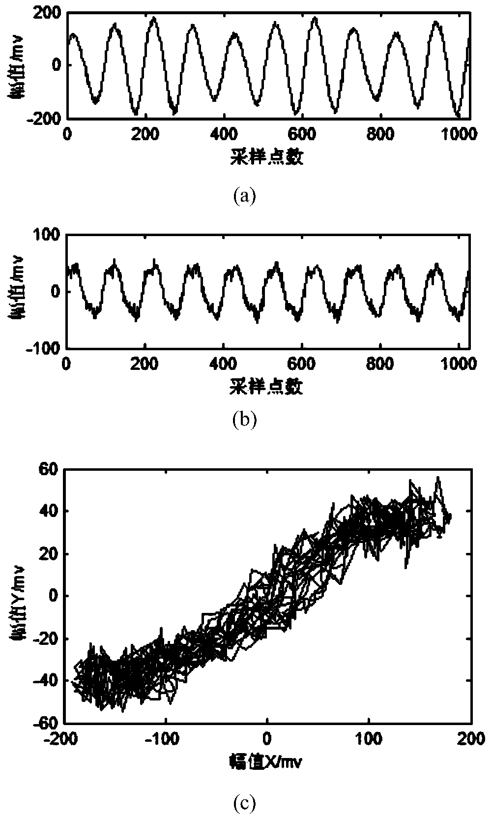
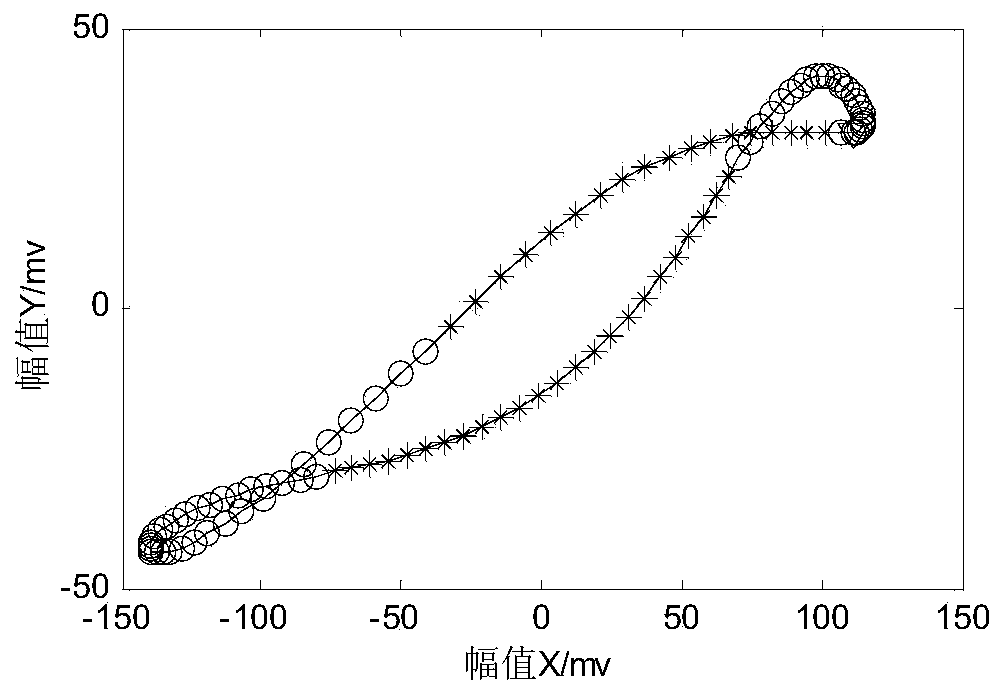
[0024] According to the method proposed by the present invention, the rotor impact grinding experiment is carried out on the Bently RK4 rotor test bench, and ...


PUM


Abstract

The invention discloses an automatic identifying method of the rotor system shaft center track precessional motion direction. Firstly, a sampling frequency is set, radial vibrating signals of a rotor are collected by means of a vibrating sensor, and an amplitude spectrum is obtained through the fast Fourier transform algorithm; secondly, main frequency content in the vibrating signals of the rotor is corrected in the phase difference correcting method, and the signals are reconstructed after correcting is conducted; finally, a rotor purification shaft center track is combined by means of the reconstructed signals, and the precessional motion direction of the whole shaft center track is obtained by means of the purification shaft center track through identification of the precessional motion directions of local arc sections. The automatic identifying method is conducted from a local angle, the precessional motion directions of various local arc sections of the shaft center track are identified, influence of the complex degree of the shaft center track is avoided, and universality is stronger.

Description

technical field [0001] The invention belongs to the technical field of trajectory detection, and in particular relates to a method for automatically identifying the precession direction of the axis trajectory of a rotor system. Background technique [0002] The axis trajectory is an important basis for judging the operating state of rotating machinery. The shape of the axis trajectory and the precession direction of the axis trajectory are two important characteristics of the axis trajectory. When the rotor is in different operating states, the shape of the axis trajectory will change, and the precession direction may also change. For example, the axis trajectory of the unbalanced fault rotor is elliptical and positive precession; the axis trajectory of the misalignment fault is banana-shaped. Or figure 8, forward and reverse precession coexist. Therefore, the operating state of the rotor can be judged by identifying the shape of the axis trajectory and the precession dire...

Claims


Application Information

Patent Timeline
IPC IPC(8): G01P13/04
Inventor 胡爱军王雪张朋波向玲袁万全李楠
Owner NORTH CHINA ELECTRIC POWER UNIV (BAODING)
Learn More