
Radio-frequency circuit structure for achieving function of converting GNSS satellite signals into baseband signals

A satellite signal and baseband signal technology, applied in the field of global navigation satellite systems, can solve problems such as cost, power consumption and volume increase, baseband processing difficulty, complex circuit structure, etc., to avoid DC offset, reduce cost, and reduce crosstalk. Effect

Inactive Publication Date: 2013-11-27
COMNAV TECH
View PDF5 Cites 20 Cited by
  • Summary
  • Abstract
  • Description
  • Claims
  • Application Information

AI Technical Summary

Problems solved by technology

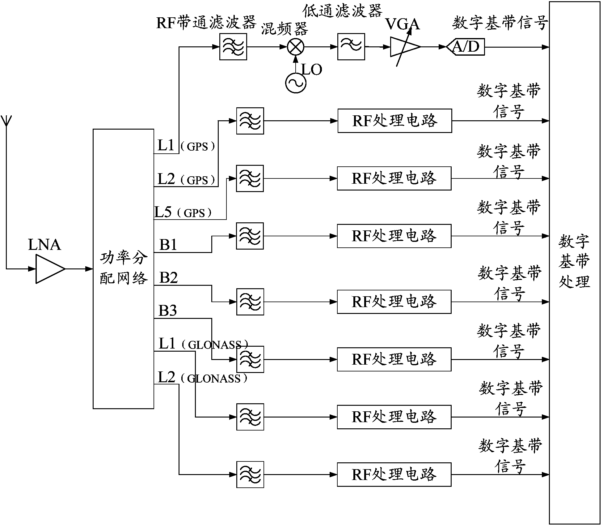
This design scheme has an extremely complex circuit structure. When dealing with GNSS multi-mode and multi-frequency satellite signals with up to 8 frequency bands, it must be equipped with numerous local oscillator circuits and frequency mixing circuits.
This brings great difficulties to the debugging of the system, and leads to a significant increase in the cost, power consumption and volume of the whole system, which runs counter to the needs of portable applications of GNSS receivers
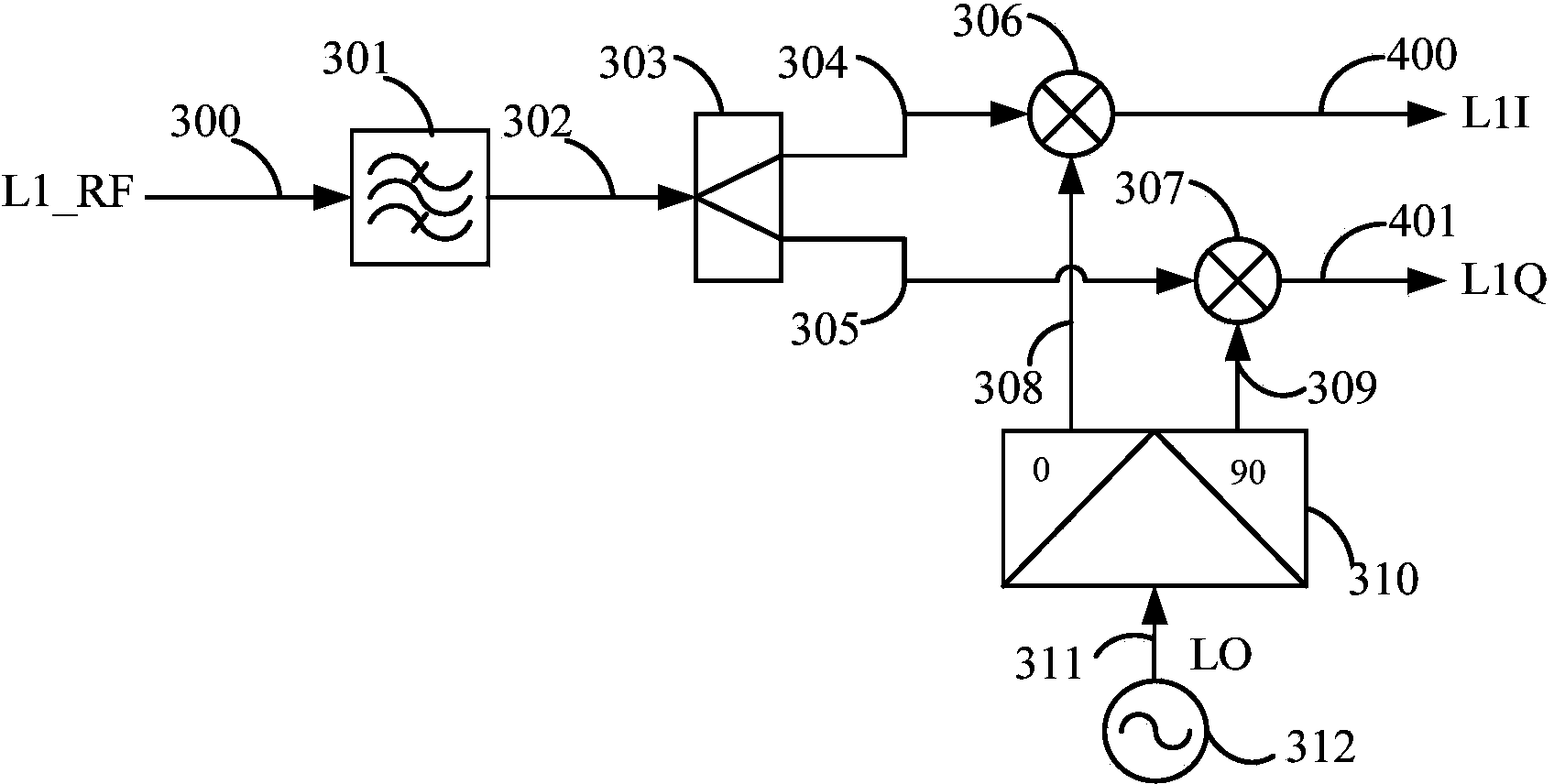
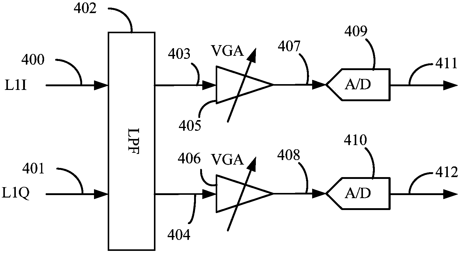
There is also a zero-IF solution, which uses a frequency conversion to directly down-convert GNSS multi-mode and multi-frequency satellite signals from the 1.15-1.65GHz frequency band to zero frequency. The circuit structure is simpler than the previous solution, but there is a problem of DC offset signals. Subsequent baseband processing brings great difficulties

Method used


Image

  • Radio-frequency circuit structure for achieving function of converting GNSS satellite signals into baseband signals
  • Radio-frequency circuit structure for achieving function of converting GNSS satellite signals into baseband signals
  • Radio-frequency circuit structure for achieving function of converting GNSS satellite signals into baseband signals

Examples


Embodiment Construction

[0032] In order to describe the technical content of the present invention more clearly, further description will be given below in conjunction with specific embodiments.

[0033] Such as figure 1 Shown is a schematic diagram of the overall structure of the radio frequency circuit structure for realizing the function of converting satellite signals of the global navigation satellite system into baseband signals according to the present invention.

[0034] Using the circuit structure of the present invention to realize the conversion of GNSS multi-mode and multi-frequency satellite signals into baseband signals includes dividing the GNSS multi-mode and multi-frequency satellite signals into GPS L1 / L2 / L5 signals and Beidou second-generation signals according to different carrier frequencies after being received by the antenna. The process of B1 / B2 / B3 signals and GLONASS L1 / L2 signals with a total of eight channels; including the process of converting GNSS multi-mode and multi-fr...


PUM


Abstract

The invention relates to a radio-frequency circuit structure for achieving the function of converting GNSS satellite signals into baseband signals. The radio-frequency circuit structure comprises a shunt function module, a plurality of frequency conversion function modules, a plurality of local oscillator signal modules and a plurality of analog-digital conversion modules. The shunt function module is used for dividing the GNSS satellite signals received by an antenna into satellite signals in a plurality of channels, each frequency conversion function module is used for conducting frequency conversion on the satellite signals in the corresponding channels to form approximate zero frequency signals, and each local oscillator signal module is used for generating local oscillator signals and outputting the local oscillator signals to the frequency conversion function modules. According to the radio-frequency circuit structure for achieving the function of converting the GNSS satellite signals into the baseband signals, the structure is adopted, therefore, frequency conversion and follow-up signal processing can be carried out on the satellite signals in each frequency band independently, the signal quality is guaranteed, the sufficient signal to noise ratio is provided for a baseband processing circuit, and the wide applied range is achieved.

Description

technical field [0001] The invention relates to the field of global navigation satellite systems, in particular to the field of radio frequency circuits of global navigation satellite system receivers, and specifically refers to a radio frequency circuit structure that realizes the function of converting satellite signals of the global navigation satellite system into baseband signals. Background technique [0002] Beidou satellite navigation system (specifically Beidou second-generation satellite navigation system), GPS (Global Navigation Satellite System, Global Positioning System), GLONASS (Glonass, the abbreviation of Global Navigation Satellite System in Russian) and Galileo (Galileo, European Satellite System) Navigation System) is a global satellite navigation and positioning system established by China, the United States, Russia and the European Union. [0003] The current mainstream navigation and positioning method refers to providing navigation data to the receive...

Claims


Application Information

Patent Timeline
Patent Type & Authority Applications(China)
IPC IPC(8): G01S19/37
CPCG01S19/36G01S19/32G01S19/33G01S19/35G01S19/37
Inventor 刘杰王永泉宋阳
Owner COMNAV TECH
Learn More