Method for designing data transmission antenna beams of space inertia oriented posture satellites

A technology of satellite data transmission and antenna beam, which is applied in the field of satellite communication, can solve the problems of resource cost, small satellites are difficult to realize, consume large resources, increase transmission power, etc., to solve the problem of on-board energy consumption, high-speed data transmission performance, reduce The effect of transmit power

Active Publication Date: 2013-11-27
NAT SPACE SCI CENT CAS
View PDF3 Cites 16 Cited by
  • Summary
  • Abstract
  • Description
  • Claims
  • Application Information

AI Technical Summary

Problems solved by technology

This requires the entire satellite to increase the transmit power (4 times) and increase the sensitivity of the receiver. These requirements are sometimes impossible to achieve in engineering, or they need to consume a lot of space and ground station resources.
[0006] In the existing technology, in order to meet the requirements of the space inertial orientation satellite for the data transmission time of the ground station, a digital antenna with a mechanical turntable can also be used. At this time, the antenna is a high-gain antenna with a narrow beam, but the mechanical turntable itself has a large weight (number times the weight of the antenna), the environmental conditions are harsh when working outside the cabin, and the product reliability is high, and it is necessary to configure a special controller to calculate the azimuth and pitch angle of the turntable in real time according to the satellite orbit and attitude data, and complete the corresponding angle. Only control can ensure that the antenna beam is stably pointed to the ground station
The above resource cost is also difficult to achieve on small satellites
[0007] In fact, within the data transmission time range of space inertial orientation and attitude satellites, the omnidirectional beam of the antenna is not used in all directions. The radiated signal is ineffective; clearly, this omnidirectional beam antenna design wastes valuable satellite transmit power resources

Method used


Image

  • Method for designing data transmission antenna beams of space inertia oriented posture satellites
  • Method for designing data transmission antenna beams of space inertia oriented posture satellites

Examples


Embodiment Construction

[0022] The present invention will be further described below in conjunction with the accompanying drawings and specific embodiments, and realized through the following technical solutions.

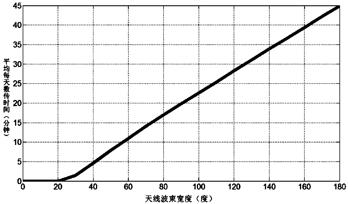
[0023] Taking a certain type of space inertial oriented attitude satellite as an example, the satellite orbit of the space inertial oriented attitude satellite is a sun-synchronous circular orbit, the orbital height is 6**km, and the orbital inclination is 9*degrees. Operational data; select Qingdao Station and Kashi Station as ground stations.

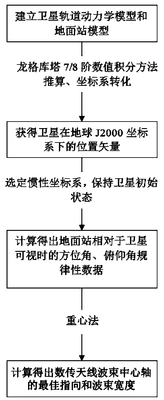
[0024] Such as figure 2 As shown, based on the in-orbit operation data obtained above, a method for designing a space inertial orientation attitude satellite data transmission antenna beam is provided, and the method includes:

[0025] Step 1), establish the orbital dynamics model and the ground station model of the space inertia orientation attitude satellite; when establishing the orbital dynamics model, can adopt the WGS84 gravitational field...


PUM


Abstract

The invention relates to a method for designing data transmission antenna beams of space inertia oriented posture satellites. Satellite borne data transmission antennas obtained by the method for designing the data transmission antenna beams of the space inertia oriented posture satellites can ensure that transmitted beams of the data transmission antennas can cover designated ground stations without adopting spherical omnibearing beam antennas or mechanical turntables, so that required data transmission time can be achieved, width of the data transmission antenna beams required for executing specific data transmission tasks can be reduced, and accordingly, a pair of narrow beam oriented antennas can replace the spherical omnibearing antennas without using the mechanical turntables. Therefore, the task data transmission time can be ensured, gain of the data transmission antennas can be improved, fast data transmission performance can be obtained, transmitting power is reduced, and the problem of energy consumption on satellites can be solved.

Description

technical field [0001] The invention relates to the field of satellite communication, in particular to a design method for a data transmission antenna beam of a space inertia orientation attitude satellite. Background technique [0002] Generally, when a low-Earth orbit satellite completes the task of payload data transmission, the data transmission antenna adopts a directional narrow beam method, which can obtain a gain of more than 3dBi, and cooperates with the spaceborne transmitter and the ground station to make the link have a sufficiently large gain. Support high-speed data transmission. This requires the satellite attitude to ensure that the transmit beam of the data transmission antenna is always pointing to the earth, so as to realize the smooth signal transmission of the satellite-ground data transmission link. However, due to the work requirements of the payload, when the satellite attitude cannot ensure that the transmit beam of the data transmission antenna poi...

Claims


Application Information

Patent Timeline
Patent Type & Authority Applications(China)
IPC IPC(8): G06F17/50
Inventor 熊蔚明程鑫叶云裳
Owner NAT SPACE SCI CENT CAS
Why Eureka
Try Eureka