

Circuit for reducing turn-on time of current control type switch adjusting system
A switching regulation and turn-on time technology, applied in the direction of high-efficiency power electronic conversion, electrical components, output power conversion devices, etc., can solve the problems of output voltage drop, affecting the normal operation of the circuit, etc. The effect of good dynamic responsiveness
- Summary
- Abstract
- Description
- Claims
- Application Information
AI Technical Summary
Problems solved by technology
Method used
Image

Examples
Embodiment approach
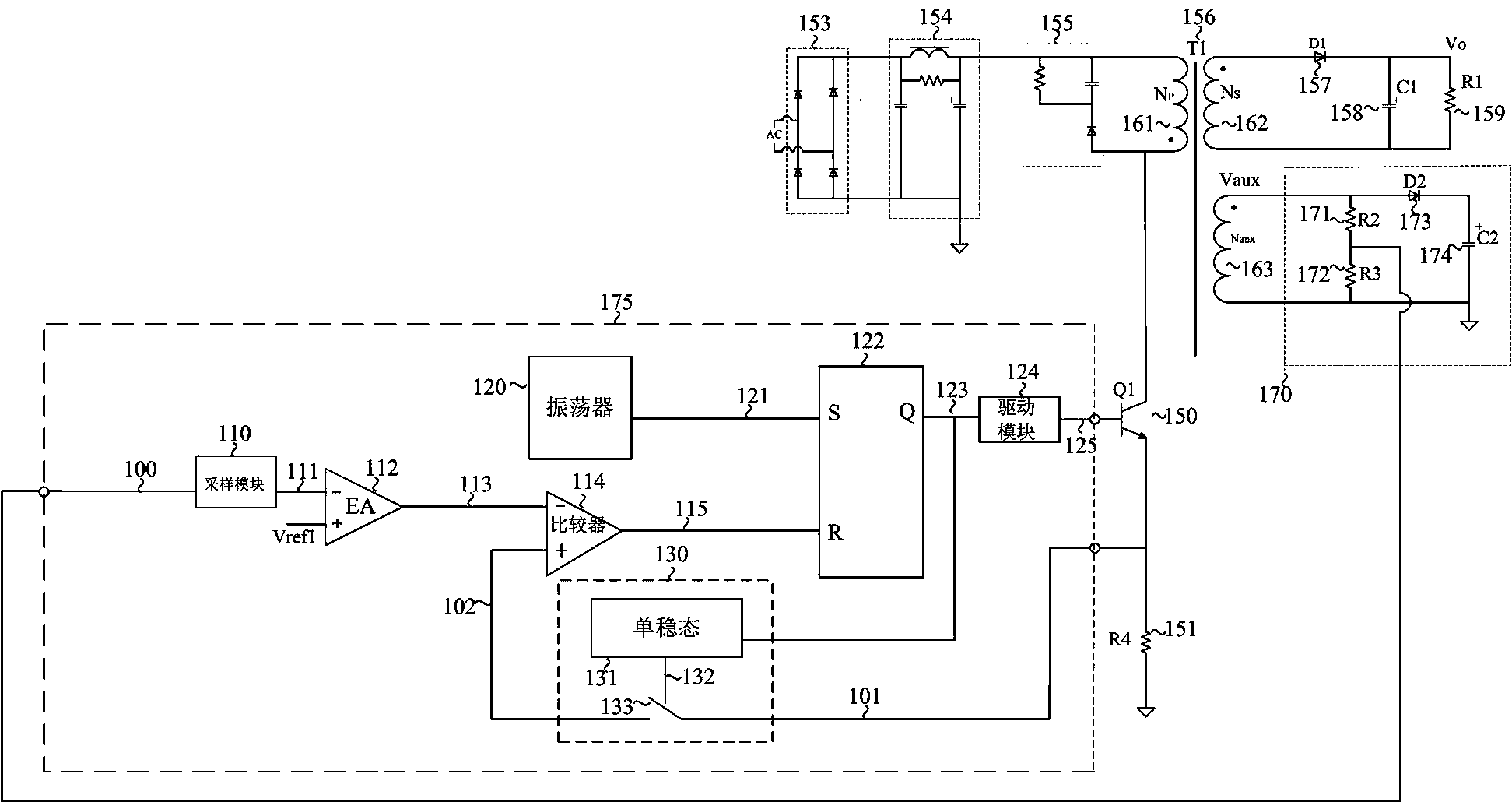
[0044] figure 1 The circuit diagram of the flyback converter built by the existing constant current and constant voltage controller fed back by the primary side; Figure 4 It is a circuit diagram of a flyback converter constructed by a circuit for reducing the turn-on time in the current control switching regulation system of the present invention. Such as figure 1 and Figure 4 As shown, the basic circuit structure of the present invention is: the constant current and constant voltage controller fed back in the existing primary side is figure 1 An exponential wave generator 440, a second comparator 442 and an OR gate 444 are added on the basis of the constant current and constant voltage controller 175 fed back by the primary side as shown, forming the reduced current control type switch regulation system of the present invention Circuit 475 for on-time.
[0045] Figure 4 It is the circuit diagram of the flyback converter built by the present invention, the circuit 475 ...
PUM
 Abstract
Description
Claims
Application Information