
Automatic electrical control cabinet

A technology of electrical control cabinets and controllers, applied in the field of control cabinets, can solve the problem that electrical control cabinets cannot meet mass production and automatic production, cannot effectively utilize the production efficiency and production quality of control cabinets, and cannot set feeding materials for electrical control cabinets The length and feeding speed and other issues can be shortened to shorten the time for adjusting and testing the feeding distance, the structure is novel, and the effect of avoiding industrial accidents is achieved.

Inactive Publication Date: 2013-11-27
KUNSHAN RUNWELL IND CONTROL
View PDF4 Cites 2 Cited by
  • Summary
  • Abstract
  • Description
  • Claims
  • Application Information

AI Technical Summary

Problems solved by technology

[0003] Today's manufacturing industry technology is changing with each passing day, especially metal stamping technology is increasingly demanding high precision and high automation. The ordinary electrical control cabinets on the market cannot meet the mass production and automated production of the hardware manufacturing industry. Fixed feeding length and feeding speed, etc., bring troubles to the production efficiency of the hardware manufacturing industry, and cannot effectively use the control cabinet to improve production efficiency and production quality

Method used


Image

  • Automatic electrical control cabinet
  • Automatic electrical control cabinet

Examples


Embodiment approach

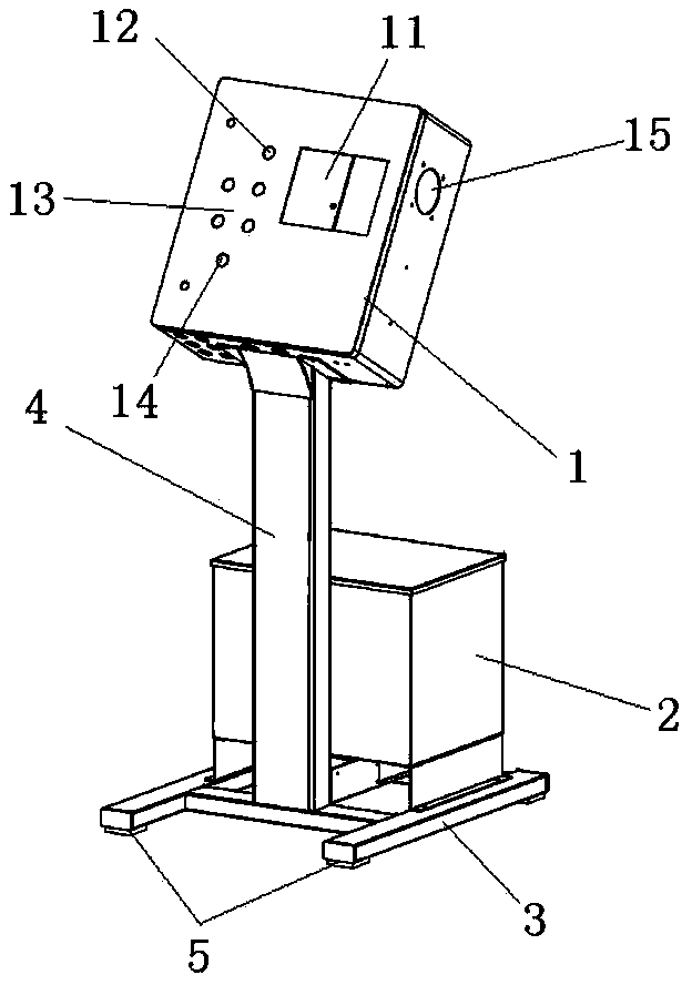
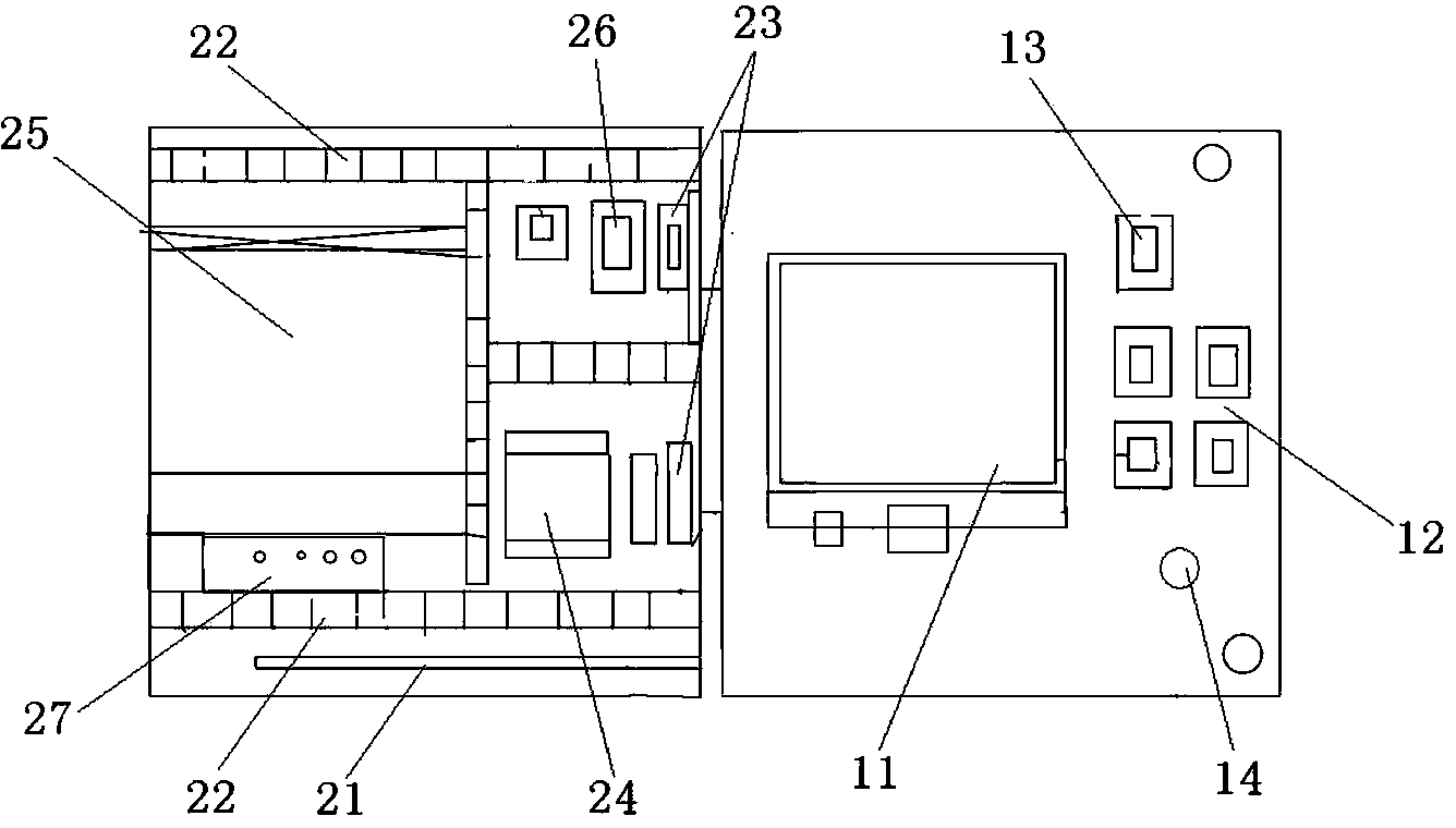
[0017] figure 1 It shows an embodiment of an automated electrical control cabinet of the present invention, comprising an upper cabinet 1, a lower cabinet 2, a bracket 3 and a support column 4, the lower cabinet 2 is arranged on the bracket 3, and the support The bottom of the column 4 is connected to the lower cabinet body 2, and the top of the support column 4 is connected to the upper cabinet body 1. The upper cabinet body 1 is inclined at an angle of 20-45 degrees. The control panel of the upper cabinet body 1 is provided with a touch control panel 11 , a control button 12, a power switch 13 and a control cabinet lock 14; the upper cabinet is provided with a terminal block 21, a trunking 22, a relay 23, a controller 24, a servo driver 25, a safety device 26 and a power supply 27; There is a transformer inside the cabinet 2; the side of the upper cabinet 1 is provided with a cooling fan 15 installed at the air outlet; At the bottom of the cabinet 1, a relay 23, a controlle...


PUM


Abstract

The invention discloses an automatic electrical control cabinet. The automatic electrical control cabinet comprises an upper cabinet body, a lower cabinet body, a bracket and a supporting column, wherein the lower cabinet body is arranged on the bracket; the bottom of the supporting column is connected with the lower cabinet body; the top of the supporting column is connected with the upper cabinet body; and the upper cabinet body is inclined at an angle of 20 to 45 degrees. The automatic electrical control cabinet is novel in structure; the upper cabinet body is inclined at an angle of 20 degrees, so that the automatic electrical control cabinet is more convenient to control; locking pulleys are arranged at the bottom of the automatic electrical control cabinet, so that the automatic electrical control cabinet is convenient to push; a mechanical or pneumatic release manner is adopted, a release point is accurate, so that the automatic electrical control cabinet can be used for a long time and is failure-free; the automatic electrical control cabinet, in a Panasonic high-quality type, is driven by a brushless servo motor, and the feeding distance adjustment time and the test time are effectively shortened; by the adoption of a high decoder, the automatic electrical control cabinet is accurate in recovery and better in feeding accuracy; by synchronous belt drive, a gear clearance can be eliminated, the abrasion is extremely low, the noise is low, the lubrication is not needed, and the motor is hidden and can be prevented from being damaged during transportation, loading and unloading.

Description

[0001] technical field [0002] The invention relates to a control cabinet, in particular to an automatic electrical control cabinet used in the hardware manufacturing industry. Background technique [0003] Today's manufacturing industry technology is changing with each passing day, especially metal stamping technology is increasingly demanding high precision and high automation. The ordinary electrical control cabinets on the market cannot meet the mass production and automated production of the hardware manufacturing industry. The fixed feeding length and feeding speed have brought troubles to the production efficiency of the hardware manufacturing industry, and it is impossible to effectively use the control cabinet to improve production efficiency and production quality. [0004] Contents of the invention [0005] In order to overcome the above defects, the present invention provides an automatic electrical control cabinet suitable for the hardware manufacturing indu...

Claims


Application Information

Patent Timeline
Patent Type & Authority Applications(China)
IPC IPC(8): H05K5/00H05K5/02
Inventor 薛振宇林刚付春新
Owner KUNSHAN RUNWELL IND CONTROL
Learn More