Bus bar for forming fuse block circuit, fuse link, and method of making fuse link

A technology of bus bars and fuses, which is applied in the manufacture of fuses, the manufacture of contact boxes/bases, circuits, etc., and can solve the problems of easy deformation and low strength of fusible parts 113

Active Publication Date: 2016-01-20
YAZAKI CORP
View PDF12 Cites 0 Cited by
  • Summary
  • Abstract
  • Description
  • Claims
  • Application Information

AI Technical Summary

Problems solved by technology

Although the narrow portion 113a is a portion that has a direct influence on the resistance value that affects the fusing characteristics of the fusible member 113, its strength is low due to the reduced material width, so the fusible member 113 is easily deformed when an external force is applied thereto.

Method used


Image

  • Bus bar for forming fuse block circuit, fuse link, and method of making fuse link
  • Bus bar for forming fuse block circuit, fuse link, and method of making fuse link
  • Bus bar for forming fuse block circuit, fuse link, and method of making fuse link

Examples


Embodiment Construction

[0047] Embodiments of the present invention will be described below with reference to the accompanying drawings.

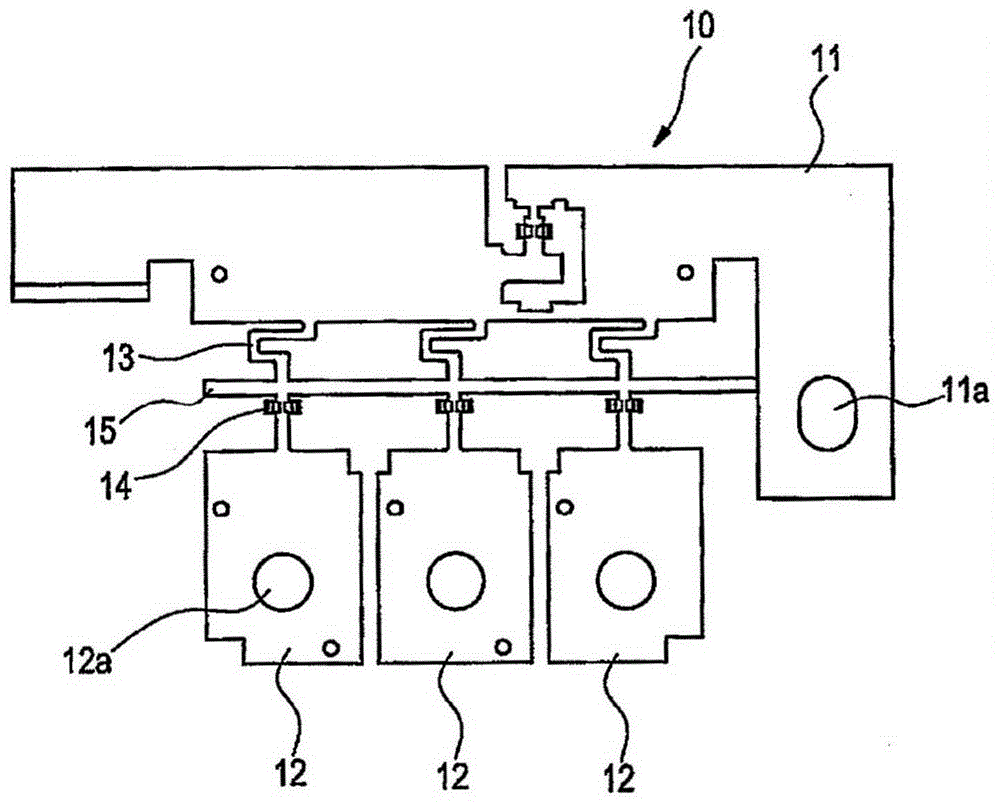
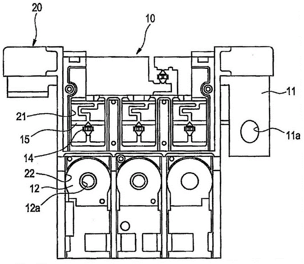
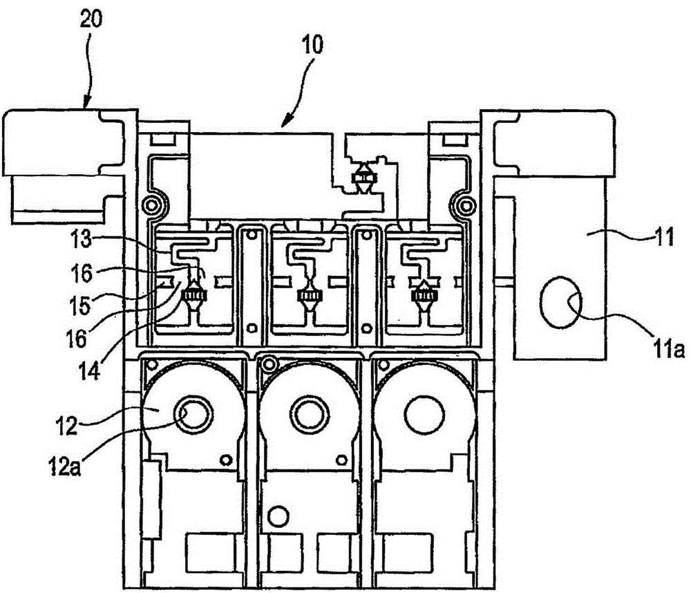
[0048] Such as Figures 1 to 3 As shown, the fuse block according to the present embodiment includes: a bus bar (circuit forming bus bar) 10 for forming a circuit, the bus bar 10 is manufactured by press-working a metal plate; and a resin case 20, the resin case 20 After the bus bar 10 is set in the mold, the bus bar 10 is insert-molded so as to partially cover the outer periphery of the bus bar 10 or the like.

[0049] Such as figure 1 As shown, the bus bar 10 includes: a power supply side terminal board 11 to be connected to the battery; and a plurality of load side terminal boards 12 via respective fusible parts 13 (a portion through which the current flows is reduced in cross-sectional area and thus easily fused due to Joule heat) is connected to the power supply side terminal board 11 so as to form a branch circuit from the power supply side terminal board...


PUM


Abstract

A bus bar (10) integrally comprising a plurality of load-side terminal strips (12) connected to a supply-side terminal strip via their respective fusible parts (13), The shape of the fusible parts is uniform, the middle part of the fusible parts in the direction of current flow is provided with a temporary connection point, and the temporary connection points of the fusible parts adjacent to each other are passed through to be cut off in a later step. Engaging ribs (15) are connected to each other, and by changing the cutting position of the engaging ribs to be cut in the later step, the fusing characteristics of the fusible part can be changed.

Description

technical field [0001] The present invention relates to a fuse block mainly inserted between a vehicle battery and a load side device, and more particularly to a bus bar for forming a circuit of the fuse block, a fuse block and a method for manufacturing the fuse block method. Background technique [0002] This type of fuse block typically includes multiple branch circuits connected to multiple loads, with fuses protecting each branch circuit. In this case, from the power supply side terminal board (which corresponds to the upstream side terminal board disposed on the upstream side in the direction of current flow) to the multi-branch load side terminal board (which A circuit corresponding to a downstream-side terminal board disposed on the downstream side in the current flow direction) is made of a pressed bus bar, and only a necessary portion thereof is covered with a case made of resin, whereby the circuit is formed into a block. [0003] Figures 5 to 7 Examples of pri...

Claims


Application Information

Patent Timeline
Patent Type & Authority Patents(China)
IPC IPC(8): H01H85/12H01H69/02H01H85/10H01H85/11
CPCH01H69/02H01H85/10H01H85/11H01H85/12Y10T29/49107H01R9/245H01R43/18
Inventor 田口直人志水胜
Owner YAZAKI CORP
Why Eureka
Try Eureka