Repeater and loopback mode switching method

A loopback mode, repeater technology, applied in electromagnetic wave transmission systems, optical fiber transmission, electrical components, etc., can solve the problems of business optical co-channel interference noise, downlink business signal-to-noise ratio decline, and inability to achieve long-distance monitoring. , to achieve the effect of large dynamic range and large signal-to-noise ratio

Active Publication Date: 2016-08-10
HUAWEI MARINE NETWORKS CO LTD
View PDF7 Cites 0 Cited by
  • Summary
  • Abstract
  • Description
  • Claims
  • Application Information

AI Technical Summary

Problems solved by technology

However, the problem with the out-to-in loopback mode is that since the backscattered light is amplified by the optical amplifier, when there is service light on the downlink line, the amplified backscattered light will cause co-frequency interference noise to the service light, Decrease the service signal-to-noise ratio on the downlink
In contrast, although the use of the out-to-out loopback mode can prevent the backscattered light from being amplified by the optical amplifier, it may not be able to achieve long-distance monitoring because the backscattered light is not amplified.

Method used


Image

  • Repeater and loopback mode switching method
  • Repeater and loopback mode switching method
  • Repeater and loopback mode switching method

Examples


Embodiment Construction

[0013] Embodiments of the present invention will be described in detail below through examples. In the various drawings and embodiments, the same reference numerals refer to the same parts or elements.

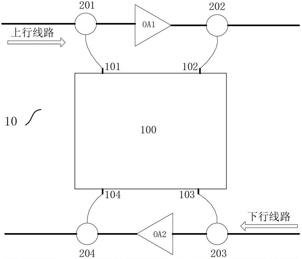
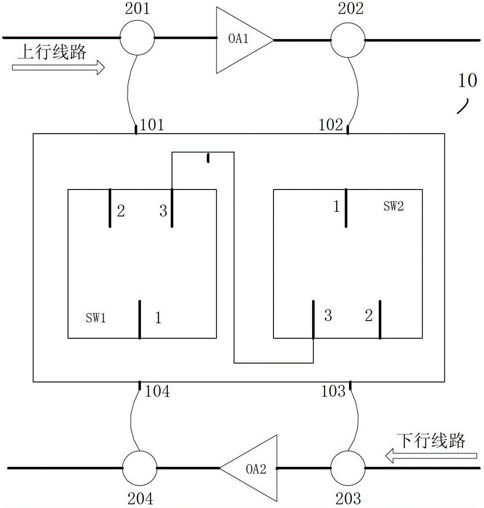
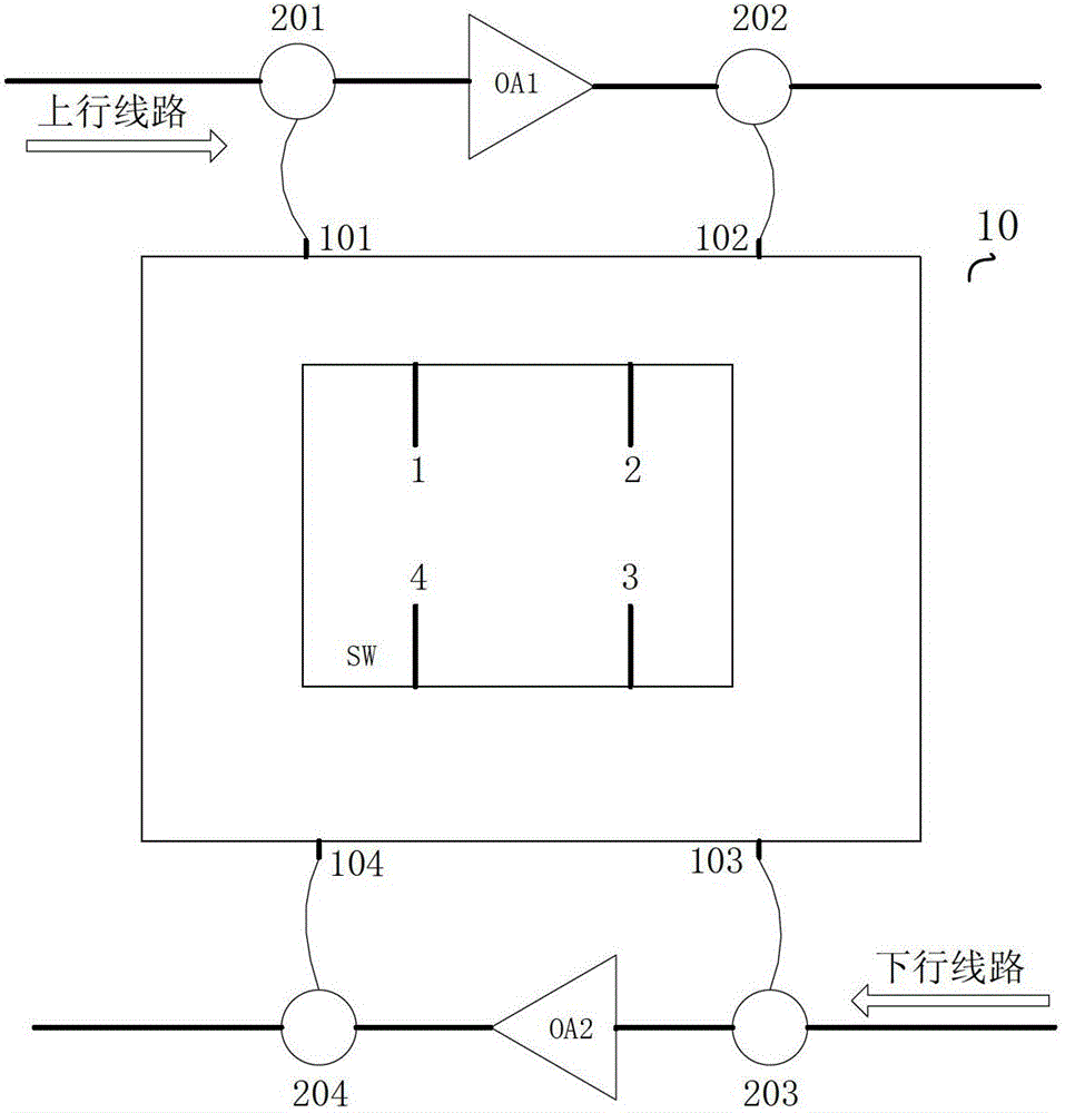
[0014] figure 1 A schematic diagram of a repeater 10 according to an embodiment of the present invention is shown. Such as figure 1 As shown, the repeater 10 according to the present invention can be coupled between the uplink and downlink of the underwater optical cable to be monitored. figure 1 The arrows in the figure show the direction of the uplink and the direction of the downlink. It should be pointed out here that the direction of the uplink and the downlink are only schematically shown here, and are not limited to the directivity shown logo. The repeater 10 may include a first optical coupler 201 , a first optical amplifier OA1 and a second optical coupler 202 sequentially connected in the uplink direction of the underwater optical cable. In addition, the repeate...


PUM


Abstract

Provided are a repeater and a loopback mode switching method. The repeater (10) comprises: a first optical coupler (201), a first optical amplifier (OA1) and a second optical coupler (202) that are connected in sequence in an uplink direction of an underwater cable, and a third optical coupler (203), a second optical amplifier (OA2) and a fourth optical coupler (204) that are connected in sequence in a downlink direction of the underwater cable. The repeater further comprises a switcher (100). The switcher comprises a first uplink terminal (101), a second uplink terminal (102), a first downlink terminal (103) and a second downlink terminal (104). The first uplink terminal is coupled to the first optical coupler, the second uplink terminal is coupled to the second optical coupler, the first downlink terminal is coupled to the third optical coupler, and the second downlink terminal is coupled to the fourth optical coupler. The switcher changes the connection relationship between the four terminals correspondingly according to a received switch indication, so that the repeater switches between an egress-to-ingress loopback mode and an ingress-to-egress loopback mode. Since the repeater can switch between the egress-to-ingress loopback mode and the ingress-to-egress loopback mode, a monitoring device is enabled to monitor a longer distance and obtain a larger dynamic range, and no co-channel interference is caused to service light in the downlink, so that a high signal-to-noise ratio of a service is obtained.

Description

technical field [0001] The invention relates to a repeater for an underwater optical cable and a loopback mode switching method. Background technique [0002] Monitoring equipment for monitoring underwater optical cables has been developed in recent years. This kind of monitoring equipment uses OTDR (OTDR: Optical Time-Domain Reflectometer (Optical Time Domain Reflectometer)) to analyze the backscattered light of the monitoring light, so as to realize the monitoring of underwater optical cables. When using monitoring equipment for monitoring, the backscattered light of the monitoring light can be obtained by forming a loop circuit between the uplink and downlink of the underwater optical cable. [0003] Generally, the loopback mode between the uplink and downlink of the underwater optical cable includes an out-to-in loopback mode and an out-to-out loopback mode. For example, when monitoring the uplink, the out-in loopback mode means that the backscattered light of the moni...

Claims


Application Information

Patent Timeline
Patent Type & Authority Patents(China)
IPC IPC(8): H04B10/297H04B10/25H04B10/071
CPCH04B10/075H04B10/2972
Inventor 苏丹郑强贾世凯
Owner HUAWEI MARINE NETWORKS CO LTD
Why Eureka
Try Eureka