Pressure equalizing control method for air purifier

A pressure equalization control and purifier technology, which is applied to chemical instruments and methods, separation methods, and dispersed particle separation, can solve the problems of shortening the life of the adsorbent, large impact of the adsorbent, and troublesome adjustment, so as to reduce the adjustment workload, The effect of reducing the influence of production conditions and stabilizing the change of gas flow rate

Active Publication Date: 2015-07-22
湖北浠水蓝天联合气体有限公司
View PDF3 Cites 1 Cited by
  • Summary
  • Abstract
  • Description
  • Claims
  • Application Information

AI Technical Summary

Problems solved by technology

The disadvantage of this control method is that there are multiple jumping valve openings, which will bring several fluctuations to the production conditions. The fluctuations of the working conditions require adjustment personnel to adjust the stable working conditions, which brings great trouble to the adjustment personnel and affects the adsorption. The impact of the solvent is also large, which will shorten the life of the adsorbent; due to manufacturing control reasons for some valves, the opening setting value of the pressure equalizing valve when the left adsorption cylinder is equalizing to the right adsorption cylinder may be different from the opening setting value when the pressure is equalizing in the reverse direction. Different, the opening setting value must be adjusted every time the pressure is equalized, which brings a lot of trouble to the adjustment; in addition, the valve opening setting value is an empirical value, and it takes many trials to determine

Method used


Image

  • Pressure equalizing control method for air purifier

Examples


Embodiment Construction

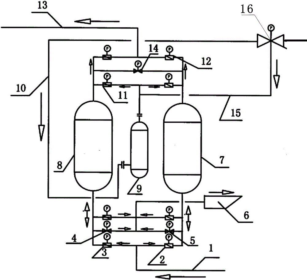
[0016] Such as figure 1 As shown, an air purifier device includes two air purifier adsorption cartridges: a first purification adsorption cartridge 8 and a second purification adsorption cartridge 7 . Air into the purifier gas pipeline 1 is divided into two paths, the first path of air and the second path of air respectively pass through the first switching valve 3 and the second switching valve 2 to connect to the bottom inlet and outlet of the first purification adsorption cylinder 8 and the second purification adsorption cylinder 7 The bottom inlet and outlet of the first purification adsorption cylinder 8 and the second purification adsorption cylinder 7 respectively pass through the first high-pressure venting electromagnetic switching valve 4 and the second high-pressure venting electromagnetic switching valve 5, and then connect the purifier dirty nitrogen regeneration blowing cold muffler 6.

[0017] After the top outlets of the first purification adsorption cylinder 8...


PUM


Abstract

The invention provides a pressure equalizing control method for an air purifier. The outlet of the air purifier is provided with a flow meter; needed air flows can be figured out when pressure equalizing of a first purify absorbing cylinder and a second purify absorbing cylinder is performed, and the calculated amount is set as a control amount L1 when the pressure equalizing is performed; when the pressure equalizing starts, the detected amount of air of the outlet of the air purifier is L, an air pressure equalizing solenoid valve is turned on slowly until the amount of air of the outlet of the air purifier is less of L1 as compared with that when pressure equalizing starts, that is to say, the amount of air of the outlet is equal to L minus L1; the air pressure equalizing solenoid valve is adjusted automatically and continuously, when the amount of air of the outlet is more than L minus L1, the air pressure equalizing solenoid is turned down automatically; when the amount of air of the outlet is less than L minus L1, the air pressure equalizing solenoid is turned up until the pressure equalizing is finished; when pressure differences between the first purify absorbing cylinder and the second purify absorbing cylinder are close to zero, the air pressure equalizing solenoid is turned off, and the pressure equalizing process of the air purifier is finished. A method of controlling the degree of turning up of a pressure equalizing valve is replaced by a method of controlling the degree of turning up in real time according to the amount of air of the outlet, and influences on production condition by the pressure equalizing process can be reduced accordingly.

Description

technical field [0001] The invention relates to a pressure equalization control method for an air purifier, which relates to the field of low-temperature rectification air separation. Background technique [0002] Air purifier is an essential production equipment for air separation production. The interior of the purifier is mainly filled with main materials such as air impurities 13X molecular sieve and moisture adsorption ceramic balls. Its main functions are: [0003] 1) Purify carbon dioxide, moisture and other mechanical impurities in compressed air. [0004] 2) The air separation plant is generally equipped with two air purifier adsorption cylinders, which are automatically controlled and switched. Other mechanical impurities such as carbon dioxide and moisture that have been adsorbed can be switched and recycled repeatedly. [0005] 3) When the No. 1 air purifier is running to the automatic switching control time program, the purifying regeneration heating, blowing...

Claims


Application Information

Patent Timeline
Patent Type & Authority Patents(China)
IPC IPC(8): B01D53/02
Inventor 杜大艳杨涛焦文艺黄万祥何洁
Owner 湖北浠水蓝天联合气体有限公司
Why Eureka
Try Eureka