Discharge pipe distributing mechanism for powder mixer

The technology of a material distribution mechanism and a material discharge pipe is used in mixers, mixer accessories, dissolving and other directions, which can solve the problem of unfavorable medicinal powder filling the entire hopper, and achieve the effects of easy modification and installation, simple structure and reduced contact amount.

Inactive Publication Date: 2013-12-04
CHENGDU XILI INVESTMENT
View PDF0 Cites 0 Cited by
  • Summary
  • Abstract
  • Description
  • Claims
  • Application Information

AI Technical Summary

Problems solved by technology

[0004] Aiming at the above-mentioned problem that the medicine powder only falls to the position below the discharge pipe when the existing powder mixer is discharged, which is not conducive to the problem that the medicine powder evenly covers the entire hopper, the present invention provides a material distribution mechanism for the discharge pipe of the powder mixer

Method used


Image

  • Discharge pipe distributing mechanism for powder mixer

Examples


Embodiment 1

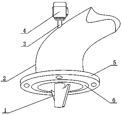
[0019] When the medicine powder is discharged from the mouth of the discharge pipe 2, the distributing head 1 rotates around its rotor driven by the motor 4, and the fin-like structure arranged on the distributing head 1 contacts with the medicine powder during the rotation process, and moves to the The drug powder exerts a force in the same direction as the contact point movement, so that the free fall movement of the drug powder in contact with the fin structure becomes a flat throwing motion during the falling process, which is beneficial to the drug powder to disperse and fall around the distribution head 1; inverted triangle The shape of the fin structure reduces the contact amount of the medicine powder passing through the area of ​​the distributing head and the fin structure of the distributing head, and part of the medicine powder can also fall to the lower part of the distributing head.

[0020] Example 2:

Embodiment 2

[0022] The motor 4 is arranged outside the discharge pipe 2 to prevent the powder from adhering to the outer wall of the motor 4 and affecting the heat dissipation of the motor 4 .

[0023] A flange 5 is also included, and the flange 5 is fixedly connected to the outlet of the discharge pipe 2 .

[0024] The flange plate 5 provided is used for the butt joint between the discharge pipe 2 and other connection pipes, and the flange connection mode is set to facilitate the disassembly and assembly of the discharge pipe 2 and other connection pipes.

[0025] The bottom surface of the flange 5 is also fixedly connected with a rubber pad 6 .

[0026] The provided rubber pad 6 is conducive to easily realizing the sealing between the inside and outside of the pipe at the joint when the discharge pipe 2 is connected to other connecting pipes.

[0027] The connection form between the transmission shaft 3 and the distribution head 1 is threaded connection.

[0028] The threaded connecti...


PUM


Abstract

The invention discloses a discharge pipe distributing mechanism for a powder mixer. The discharge pipe distributing mechanism comprises a discharge pipe (2) and a distributing mechanism body. The distributing mechanism body comprises a distributing head (1) with at least two inverted-triangle-shaped fins evenly distributed on the lateral sides, a transmission shaft (3) and a motor (4). The distributing head (1) is located at the center of a discharge outlet of the discharge pipe. One end of the distributing head (1) is fixedly connected with the transmission shaft (3). The other end of the transmission shaft (3) is fixedly connected with a rotary shaft of the motor (4). By the discharge pipe distributing mechanism, powder can evenly distribute over the whole hopper favorably without human interference. The amount of power, passing the rotating area of the distributing head, which is in contact with the fins is reduced by the fins, and part of the powder can drop right below the distributing head. In addition, the discharge pipe distributing mechanism is simple in structure and easy to mount and modify on existing equipment.

Description

technical field [0001] The invention relates to the field of pharmaceutical powder mixer equipment, in particular to a material distribution mechanism of a discharge pipe of a powder mixer. Background technique [0002] In the process of making tablets or pills in pharmaceutical companies, fully mixing the components of the drug in a certain proportion is one of the most important steps in the process. The powder mixer is the core equipment in this process. [0003] In the prior art, the components of the medicine prepared in a certain proportion are put into the mixing barrel of the powder mixer, and after the components are mixed evenly under the action of the stirring device of the powder mixer, the material distribution mechanism of the discharge pipe of the powder mixer Discharged into the hopper to prepare for the next pelleting or tableting process. However, after the medicine powder comes out of the discharge pipe, it is piled up in pairs at the lower part of the d...

Claims


Application Information

Patent Timeline
IPC IPC(8): B01F15/02
Inventor 何明
Owner CHENGDU XILI INVESTMENT
Why Eureka
Try Eureka