Numerical control machine tool cutting force load simulation device and method

A technology of CNC machine tools and loading devices, which is applied in the direction of metal processing equipment, metal processing machinery parts, measuring/indicating equipment, etc., which can solve the problems of not meeting the processing requirements, reducing the processing accuracy, and not being able to truly reflect the cutting process of the machine tool, etc. , to achieve the effect of improving the machining accuracy of the whole machine

Inactive Publication Date: 2013-12-04
XI AN JIAOTONG UNIV
View PDF3 Cites 30 Cited by
  • Summary
  • Abstract
  • Description
  • Claims
  • Application Information

AI Technical Summary

Problems solved by technology

[0002] The rigidity of the machine tool and the rigidity of the parts are an important factor affecting the machining accuracy of the CNC machine tool. Insufficient rigidity will lead to a decrease in the machining accuracy and fail to meet the processing requirements. Therefore, a set of cutting force simulation loading device is designed to test the overall machining accuracy of the machine tool. Machine stiffness and component stiffness are essential
At present, although some corresponding loading devices have been developed to detect the stiffness of the machine tool spindle, most of the loading devices can only simulate the cutting force in one direction under static action, or simulate the application of cutting force in one direction when the spindle is working. cutting force
This is somewhat different from the cutting process of the actual machine tool, and cannot truly reflect the actual cutting process of the machine tool.

Method used


Image

  • Numerical control machine tool cutting force load simulation device and method
  • Numerical control machine tool cutting force load simulation device and method

Examples


Embodiment Construction

[0032] The present invention will be described in further detail below in conjunction with the accompanying drawings.

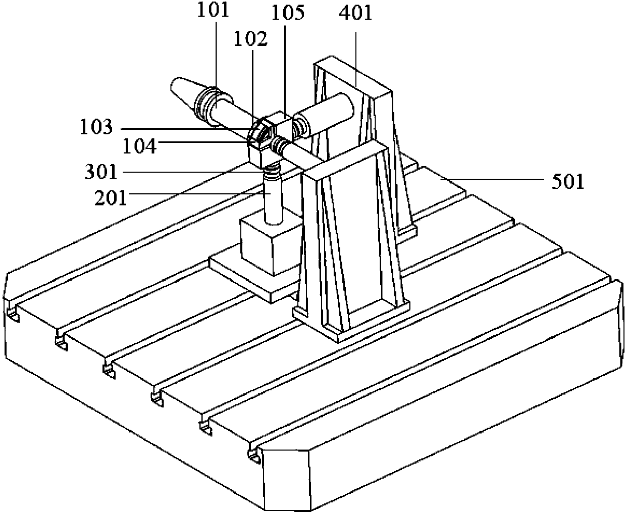
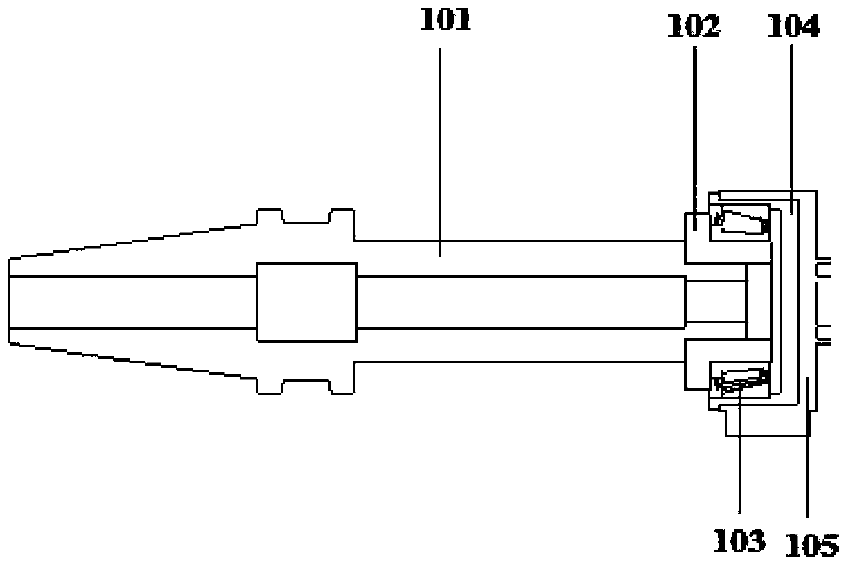
[0033] see figure 1 and figure 2 , the numerically controlled machine tool cutting force simulation loading device of the present invention comprises the simulation cutter device that can bear radial force and axial force simultaneously, is provided with the displacement sensor that detects its displacement on the simulation cutter device, and simulation cutter device comprises handle of a knife 101, handle of a knife A shank nut 102 is installed at one end of the shank nut 102, and a bearing 103 (that is, a tapered roller bearing or an angular contact ball bearing) capable of bearing radial force and axial force is set on the shank nut 102. The outer side of the bearing 103 is installed with The shaft sleeve 104 matching the size of the bearing 103 is provided with a stepped hole matching the size of the outer ring of the bearing 103 inside the shaft sleev...


PUM


Abstract

The invention provides a numerical control machine tool cutting force load simulation device and method. The device comprises a simulation tool device capable of bearing a radial force and an axial force simultaneously, a fixed device is installed at one end of the simulation tool device, a detection device for detecting magnitude of three-way acting forces of the simulation tool device is installed on the fixed device, and the detection device is further fixedly connected with a power device for providing three-way simulation cutting forces for the simulation tool device. After the devices are connected well, the pressure of the power device is adjusted, displacement and deformation of a measuring point are measured in the operating state of a machine tool, and therefore the rigidity of the whole machine tool and the rigidity of the parts can be obtained. According to the device, the three-way acting forces can be simultaneously applied to a machine tool spindle in the normal operating state of the machine tool spindle to simulate an actual machine tool cutting force, and therefore a rigidity chain composed of the rigidity of the whole machine tool and the rigidity of the parts of the machine tool is tested. A weak link in the rigidity chain is found out according to a test result, optimization design is performed on the weak link, and therefore the machining accuracy of the whole machine tool is improved.

Description

technical field [0001] The invention belongs to the field of mechanical devices, and relates to a cutting force simulation loading device and method for a numerically controlled machine tool. Background technique [0002] The rigidity of the machine tool and the rigidity of the parts are an important factor affecting the machining accuracy of the CNC machine tool. Insufficient rigidity will lead to a decrease in the machining accuracy and fail to meet the processing requirements. Therefore, a set of cutting force simulation loading device is designed to test the overall machining accuracy of the machine tool. Machine stiffness and component stiffness are essential. At present, although some corresponding loading devices have been developed to detect the stiffness of the machine tool spindle, most of the loading devices can only simulate the cutting force in one direction under static action, or simulate the application of cutting force in one direction when the spindle is wo...

Claims


Application Information

Patent Timeline
Patent Type & Authority Applications(China)
IPC IPC(8): B23Q17/09
Inventor 李宝童洪军尹彦阳高羡明甄宜超刘志刚
Owner XI AN JIAOTONG UNIV
Why Eureka
Try Eureka