Occupant protection device
A technology for protecting devices and occupants, which is applied in the directions of pedestrian/occupant safety arrangement, transportation and packaging, and thin material handling.
- Summary
- Abstract
- Description
- Claims
- Application Information
AI Technical Summary
Problems solved by technology
Method used
Image

Examples
no. 1 example
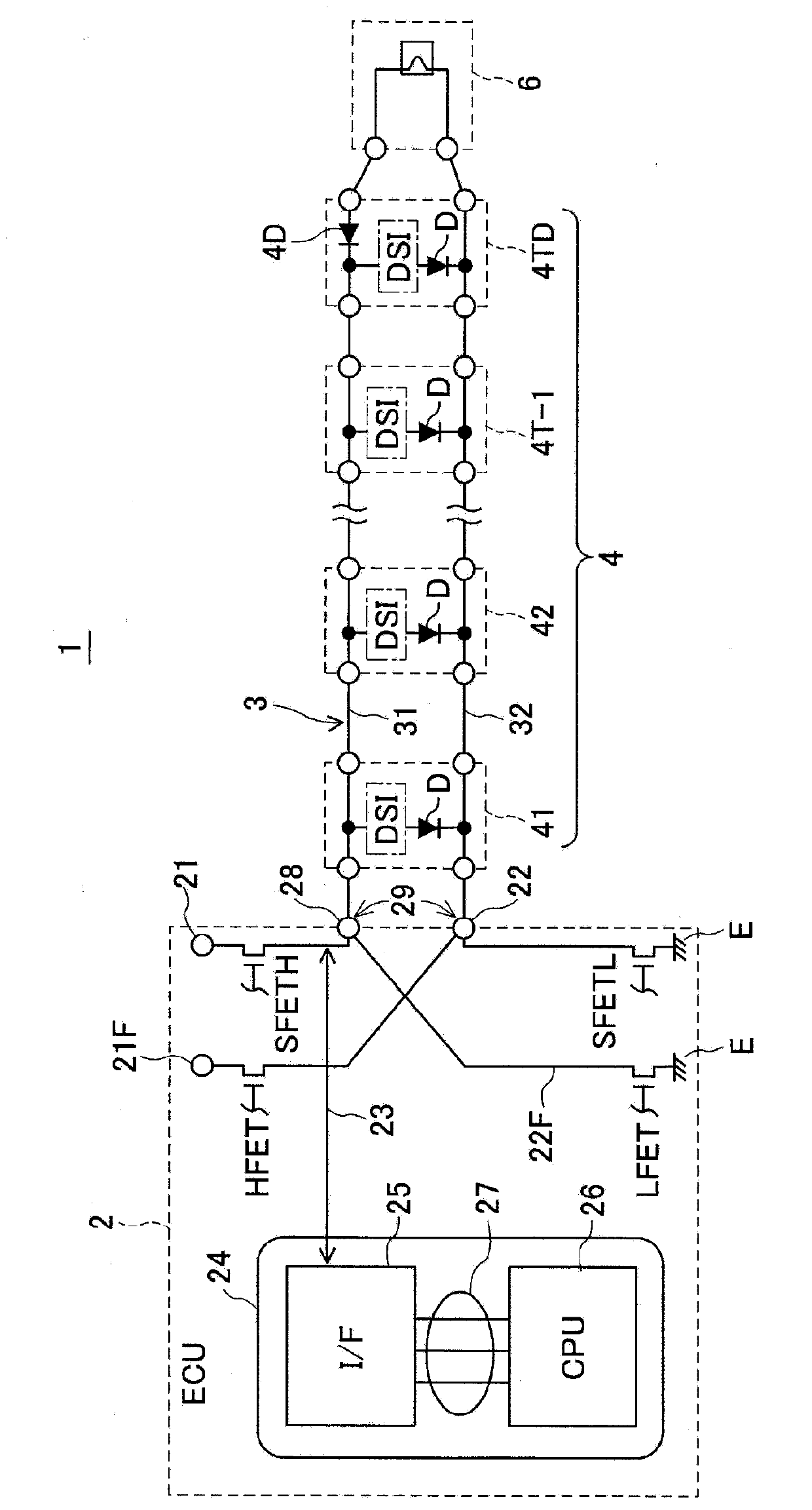
[0022] (Configuration of the first embodiment)
[0023] Such as figure 1 As shown, the occupant protection device 1 according to the first embodiment of the present disclosure is provided with an airbag ECU 2 , a two-wire parallel connection bus 3 whose base part is connected to the ECU 2 , a plurality of auxiliary sensors connected in series to the parallel connection bus 3 41 , 42 , . . . , 4T-1 , 4TD and squib 6 connected to parallel connection bus 3 .
[0024] The technical feature of the first embodiment may be that the squib 6 connected in series to the accident prevention diode 4D is connected at the terminal of the parallel connection bus 3 and the ECU 2 is used to apply the ignition voltage to the squib 6 at the time of collision, so that the squib 6 applied to the squib The firing voltage of tube 6 has the opposite polarity to the sensor driving voltage. That is, in the case where the control board 24 of the ECU 2 determines that a collision has occurred based on t...
no. 2 example
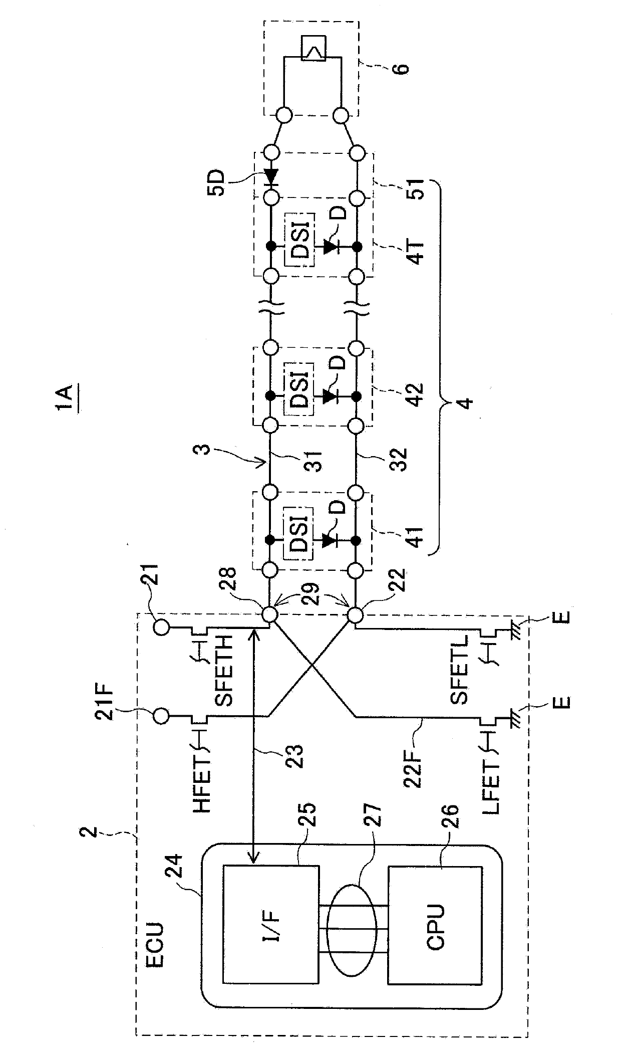
[0050] (Configuration and technical effects of the second embodiment)
[0051] In the occupant protection device according to the second embodiment of the present disclosure, as image 3 As shown, an accident prevention diode 6D is included in a two-terminal squib 6A connected to a terminal of the parallel connection bus 3 .
[0052] Therefore, the auxiliary sensors 41 , 42 , and 4T constituting the auxiliary sensor array 4 can all have the same specifications. Compared to the first embodiment, there is no need to insert accident prevention diodes into auxiliary sensors in the terminals of the parallel connection bus 3 .
[0053] Therefore, according to the first modified example of the second embodiment, in addition to obtaining similar technical effects to those of the first embodiment, protection against accidental explosion can be improved when auxiliary sensors are added, for example, by design changes.
[0054] (First Modification of Second Embodiment)
[0055] As a f...
no. 3 example
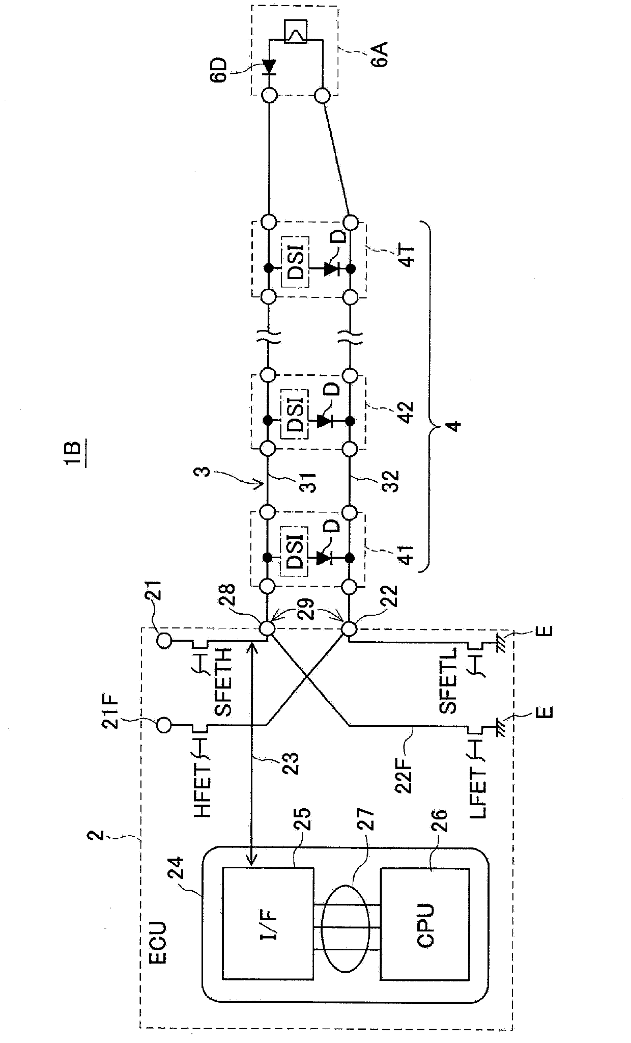
[0058] (Configuration and Technical Effects of the Third Embodiment)
[0059] Such as Figure 5 As shown, the occupant protection device 1D according to the third embodiment of the present disclosure includes a four-terminal squib 6B connectable in the middle of the parallel connection bus 3 . The four-terminal squib 6B includes an accident prevention diode 6D. The squib 6B is inserted into the base portion of the parallel connection bus 3 and connected to the vicinity of the connection port 29 of the ECU 2 . According to the third embodiment, of the two lines 31 , 32 connecting the bus 3 in parallel, only the portion between the ECU 2 and the squib 6B can resist a large current.
[0060] According to the third embodiment, even when a large current flows to the squib 6B through the ignition voltage in a collision, the large current does not flow over the squib 6B to the auxiliary sensor array 4, so that the auxiliary sensor array 4 is protected from the large current . The...
PUM
 Abstract
Description
Claims
Application Information
 - Generate Ideas
- Intellectual Property
- Life Sciences
- Materials
- Tech Scout
- Unparalleled Data Quality
- Higher Quality Content
- 60% Fewer Hallucinations
Browse by: Latest US Patents, China's latest patents, Technical Efficacy Thesaurus, Application Domain, Technology Topic, Popular Technical Reports.
© 2025 PatSnap. All rights reserved.Legal|Privacy policy|Modern Slavery Act Transparency Statement|Sitemap|About US| Contact US: help@patsnap.com