Solid State Lighting Device

A lighting device and solid-state technology, which is applied to lighting devices, lighting device parts, lighting and heating equipment, etc., to achieve the effects of miniaturization, easy miniaturization, and improvement of light extraction efficiency

Inactive Publication Date: 2014-10-01
TOSHIBA LIGHTING & TECH CORP
View PDF0 Cites 7 Cited by
  • Summary
  • Abstract
  • Description
  • Claims
  • Application Information

AI Technical Summary

Problems solved by technology

The irradiation uni

Method used


Image

  • Solid State Lighting Device
  • Solid State Lighting Device
  • Solid State Lighting Device

Examples


Embodiment Construction

[0015] Hereinafter, embodiments of the present invention will be described with reference to the accompanying drawings.

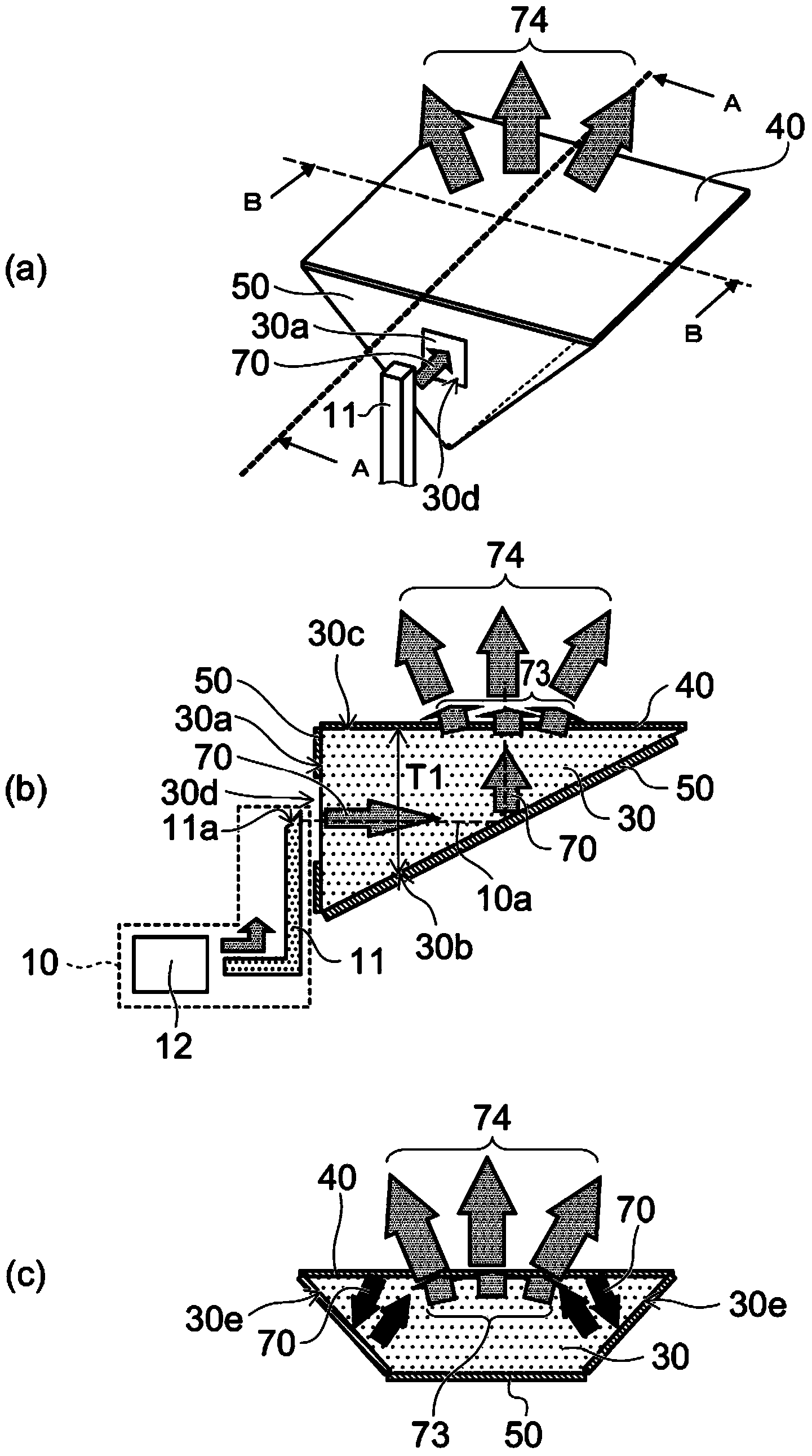
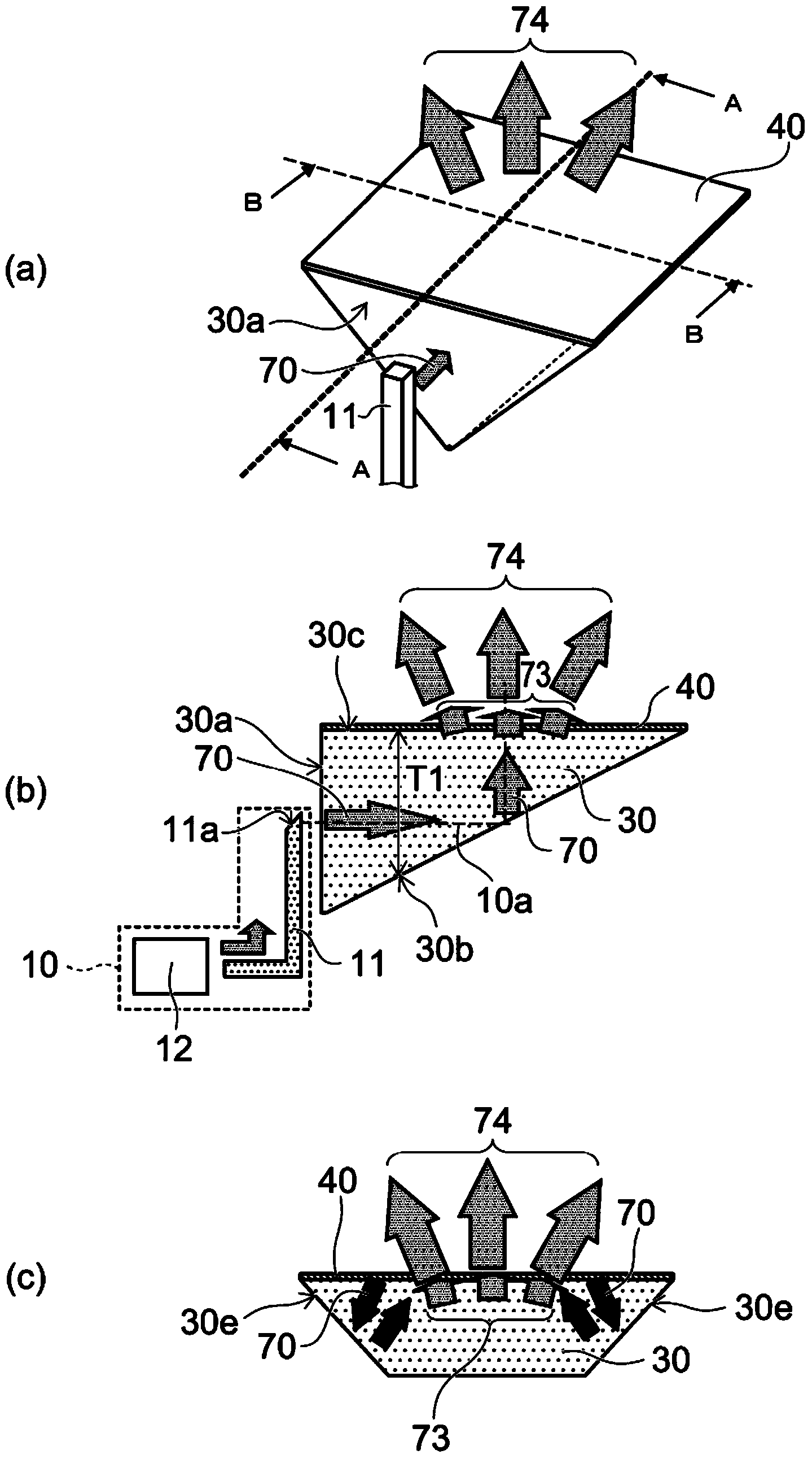
[0016] figure 1 (a) is a schematic perspective view of the solid-state lighting device according to the first embodiment, figure 1 (b) is a schematic cross-sectional view along line A-A, figure 1 (c) is a schematic cross-sectional view along line B-B.

[0017] The solid-state lighting device includes an irradiation unit 10 , a light guide body 30 , a wavelength conversion layer 40 , and a reflection unit 50 .

[0018] The irradiation unit 10 may include a semiconductor laser 12 that emits laser light 70 and an incident light guide unit 11 . The wavelength of the laser light 70 can be set to wavelengths such as ultraviolet light (380 nm) to blue light (490 nm). The light guide portion 11 may be, for example, an optical fiber or the like.

[0019] The light guide body 30 has an incident surface 30 a into which the laser light 70 is introduced, an incline...


PUM


Abstract

According to one embodiment, a solid state lighting device includes an irradiating section (10), an optical waveguide body (30), a reflecting section (50), and a first wavelength conversion layer (40). The irradiating section (10) emits laser light (70). The optical waveguide body (30) includes an incident surface into which the laser light is led (70), an inclined surface crossing an optical axis of the laser light (70), and an emission surface. The thickness between the inclined surface and the emission surface decreases as the inclined surface and the emission surface are further away from the incident surface. The reflecting section (50) is provided on the inclined surface. The first wavelength conversion layer (40) is provided on the inclined surface and configured to emit wavelength-converted light (73) having a wavelength larger than the wavelength of the laser light (70) and emit the laser light (70) as scattered light. Mixed light of the scattered light and the wavelength-converted light (73) is emitted to above the emission surface.

Description

technical field [0001] The present invention relates to a solid-state lighting device. Background technique [0002] LED (Light Emitting Diode) has become the mainstream as a light source of a white solid state lighting (SSL: Solid State Lighting) device using a solid state light emitting element. [0003] In this case, the LED chip is usually mounted on a substrate for heat dissipation and power supply, and a white light-emitting portion having a phosphor is provided so as to cover the LED chip. On the other hand, if the white light-emitting portion is composed of only the optical system, heat generation is reduced, the size and weight can be reduced, and the degree of freedom of design of the lighting device can be improved. [0004] For this purpose, white light emission can be obtained by effectively combining laser light from a semiconductor laser in the blue-violet to blue wavelength range with a light guide or the like, and irradiating a wavelength conversion layer s...

Claims


Application Information

Patent Timeline
IPC IPC(8): F21S2/00F21V8/00F21V13/04
CPCG02B6/0066F21K9/56G02B6/0043F21V9/16G02B6/003G02B6/0028F21Y2101/025G02B6/0046F21K9/52G02B6/0055G02B6/0033G02B6/0035F21V13/08F21Y2101/00F21K9/61F21K9/64F21Y2115/30F21V9/32F21V9/38H01S5/0071H01S5/0087F21V9/08G02B6/0001
Inventor 松叶庆晓
Owner TOSHIBA LIGHTING & TECH CORP
Why Eureka
Try Eureka