Cooling water circulating system

A circulation system and cooling water technology, applied in the field of circulation system, can solve the problems of not being environmentally friendly, unable to meet the needs of heat exchange, and consuming large electric energy, and achieve the effect of no pollution, simple structure, and high cooling efficiency

Inactive Publication Date: 2013-12-04
沈金根
View PDF0 Cites 2 Cited by
  • Summary
  • Abstract
  • Description
  • Claims
  • Application Information

AI Technical Summary

Problems solved by technology

[0003] There are two methods for traditional cooling water heat dissipation. One is to rely on cooling water towers for cooling. This method is mostly used in southern regions. This cooling method consumes a lot of electricity and is not environmentally friendly.
[0004] Another method of cooling water to dissipate heat is to set up a reservoir outdoors and use natural heat dissipation for cooling. This method works well in winter and is mostly used in northern regions. However, in hot summer, because the water temperature is too high, this method Unable to meet the needs of heat exchange

Method used


Image

  • Cooling water circulating system
  • Cooling water circulating system

Examples


Embodiment 1

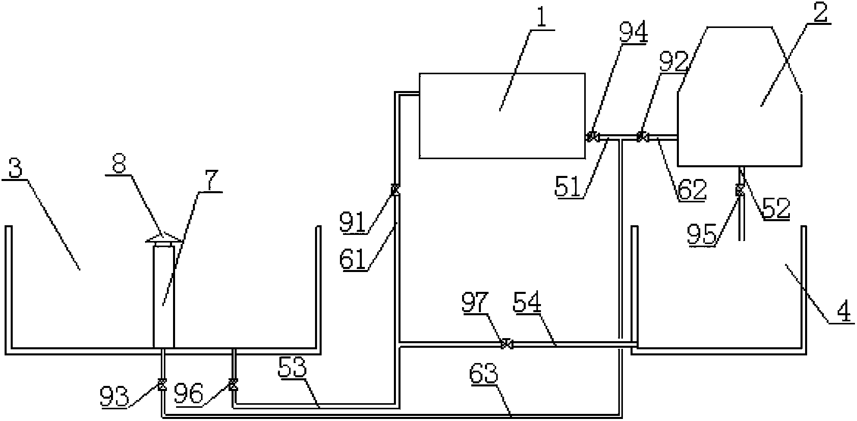
[0017] Embodiment 1 of the present invention: as figure 1 As shown, the cooling water circulation system includes a condenser 1, a cooling water tower 2, an outdoor reservoir 3 and an indoor reservoir 4, and the outlet pipe A51 of the condenser 1 is respectively connected to the water inlet pipe B62 of the cooling tower 2 and the outdoor reservoir 3 The water inlet pipe C63 of the cooling water tower 2 is connected to the indoor reservoir 4; the water inlet pipe A61 of the condenser 1 is respectively connected to the outlet pipe D54 of the indoor reservoir 4 and the outlet pipe C53 of the outdoor reservoir 3; The water storage tank 3 is provided with a cooling water spray pipe 7; the cooling water spray pipe 7 is located at the bottom center position of the outdoor water storage tank 3, and the water inlet pipe C63 of the outdoor water storage tank 3 is connected with the bottom of the cooling water spray pipe 7; The top of the water spray pipe 7 is provided with a water block...

Embodiment 2

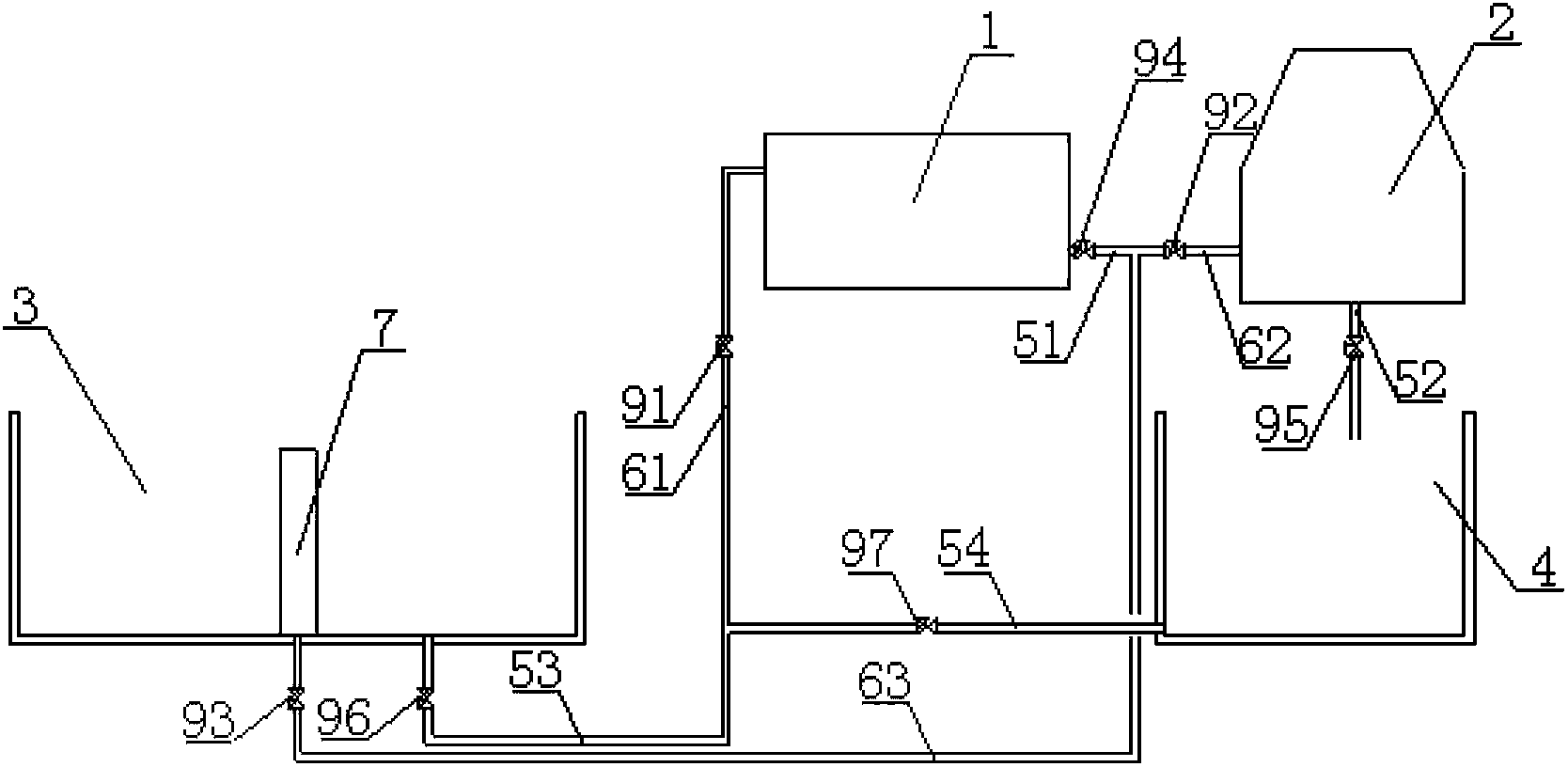
[0018] Embodiment 2 of the present invention: as figure 2 As shown, the cooling water circulation system includes a condenser 1, a cooling water tower 2, an outdoor reservoir 3 and an indoor reservoir 4, and the outlet pipe A51 of the condenser 1 is respectively connected to the water inlet pipe B62 of the cooling tower 2 and the outdoor reservoir 3 The water inlet pipe C63 of the cooling water tower 2 is connected to the indoor reservoir 4; the water inlet pipe A61 of the condenser 1 is respectively connected to the outlet pipe D54 of the indoor reservoir 4 and the outlet pipe C53 of the outdoor reservoir 3; The water storage tank 3 is provided with a cooling water spray pipe 7; the cooling water spray pipe 7 is located at the bottom center of the outdoor water storage tank 3, and the water inlet pipe C63 of the outdoor water storage tank 3 is connected with the bottom of the cooling water spray pipe 7; The water pipe A61 is provided with a valve A91, the water inlet pipe B6...


PUM


Abstract

The invention discloses a cooling water circulating system which comprises a condenser (1), a cooling water tower (2), an outdoor water storage pool (3) and an indoor water storage pool (4). A water outlet pipe A (51) of the condenser (1) is respectively connected with a water inlet pipe B (62) of the cooling water tower (2) and a water inlet pipe C (63) of the outdoor water storage pool (3). A water outlet pipe B (52) of the cooling water tower (2) is connected with the indoor water storage pool (4). A water inlet pipe A (61) of the condenser (1) is respectively connected with a water outlet pipe D (54) of the indoor water storage pool (4) and a water outlet pipe C (53) of the outdoor water storage pool (3). Two cooling modes can be achieved at the same time, and the cooling water circulating system can be used freely in a matched mode according to the seasons, and has the advantages of being simple in structure, saving energy and being environmentally friendly.

Description

technical field [0001] The invention relates to a circulation system, in particular to a cooling water circulation system. Background technique [0002] Cold storage usually needs cooling water for heat exchange during refrigeration. The traditional method is to use water as the cooling medium. After heat exchange, the high-temperature water is cooled by the cooling water tower and becomes low-temperature water again for recycling. [0003] There are two methods for traditional cooling water heat dissipation. One is to rely on cooling water towers for cooling. This method is mostly used in southern regions. This cooling method consumes a lot of electricity and is not environmentally friendly. [0004] Another method of cooling water to dissipate heat is to set up a reservoir outdoors and use natural heat dissipation for cooling. This method works well in winter and is mostly used in northern regions. However, in hot summer, because the water temperature is too high, this met...

Claims


Application Information

Patent Timeline
Patent Type & Authority Applications(China)
IPC IPC(8): F25D17/02
Inventor 沈金根
Owner 沈金根
Why Eureka
Try Eureka