
Electro-optical modulator

An electro-optic modulator and electrode technology, which is applied in instruments, optics, nonlinear optics, etc., can solve the problems of unreasonable electrode settings, high half-wave voltage, and high power consumption.

Inactive Publication Date: 2013-12-04
HONG FU JIN PRECISION IND (SHENZHEN) CO LTD +1
View PDF7 Cites 1 Cited by
  • Summary
  • Abstract
  • Description
  • Claims
  • Application Information

AI Technical Summary

Problems solved by technology

However, the existing electro-optic modulators require high half-wave voltage and high power consumption due to unreasonable electrode settings.

Method used


Image

  • Electro-optical modulator
  • Electro-optical modulator
  • Electro-optical modulator

Examples


Embodiment Construction

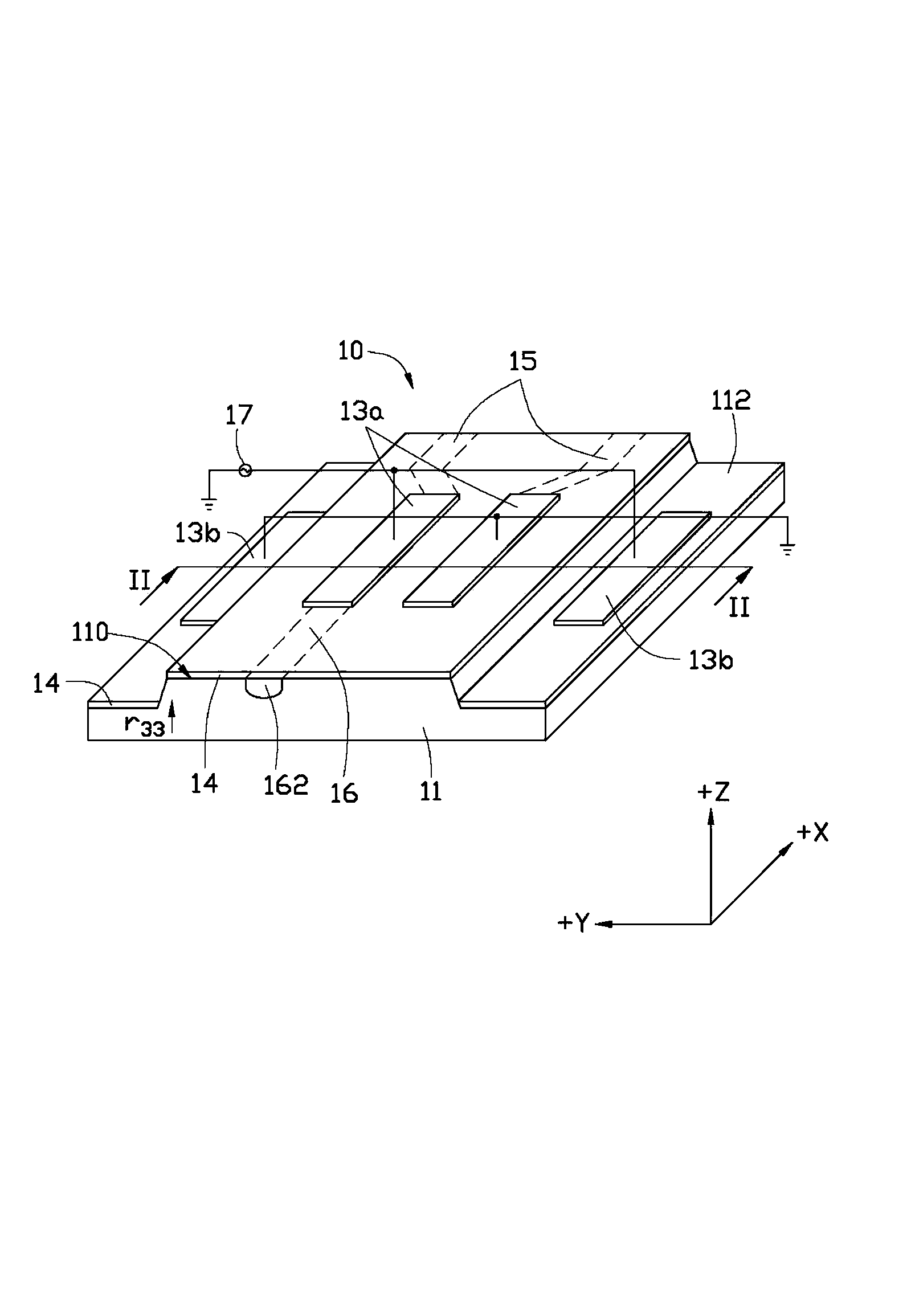
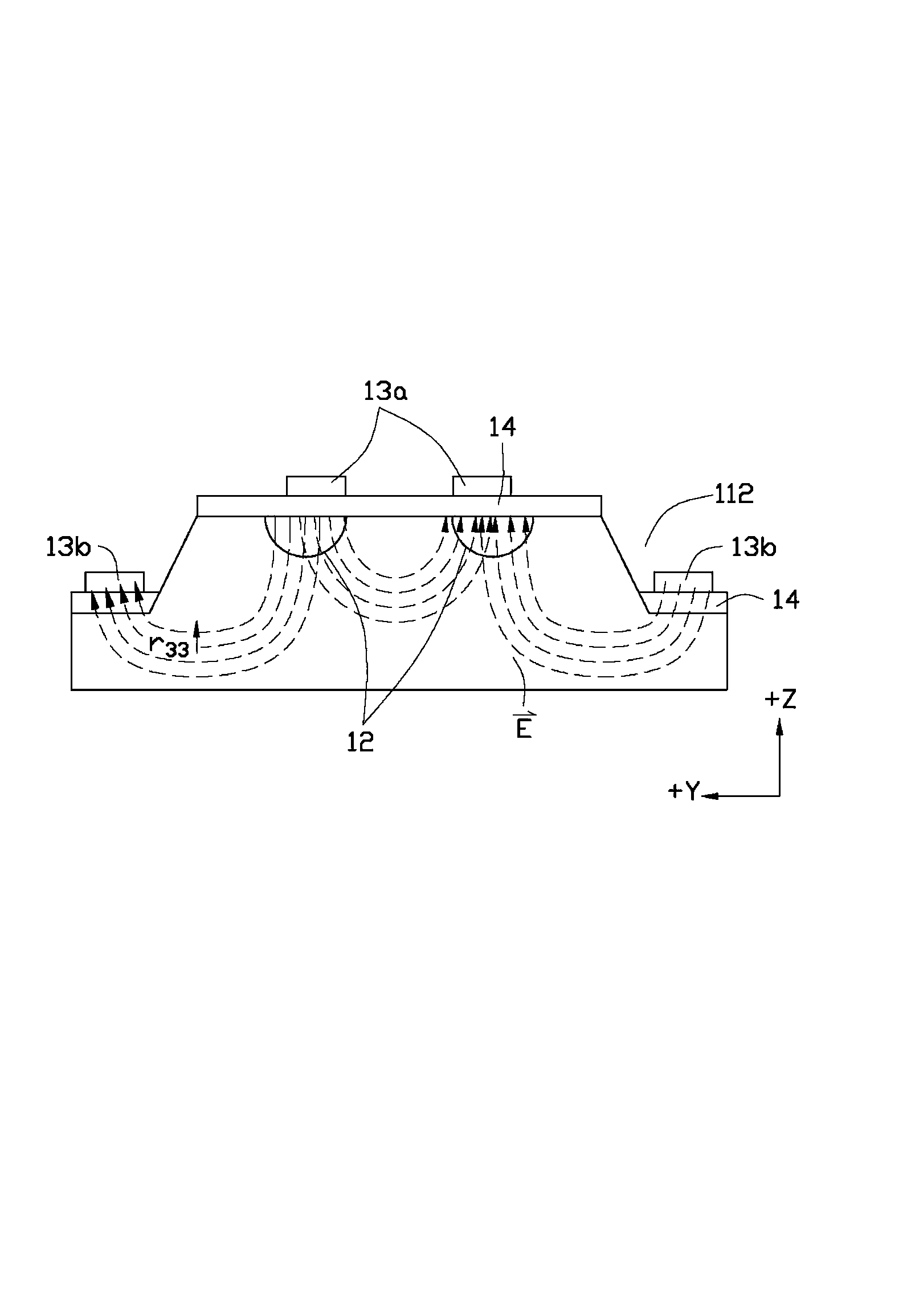
[0011] see figure 1 and figure 2 The electro-optic modulator 10 in a preferred embodiment of the present invention includes a substrate 11, a pair of optical waveguides 12 formed by inward diffusion from a first surface 110 of the substrate 11, and are parallel to each other, and a pair of optical waveguides 12 arranged on the first surface 110 On a surface 110, a first electrode 13a aligned with the pair of optical waveguides 12 and matched in shape, and a pair of second electrodes 13b disposed on both sides of the first electrode 13a and parallel to the first electrode 13a.

[0012] In this way, the electric field between the pair of first electrodes 13a and the pair of second electrodes 13b (see figure 2 ) and the electro-optical overlap integral factor (i.e. electric field The overlapping portion with the light field) is the largest, and can reach the size of the entire light field (that is, the size of the cross-sectional area of ​​the pair of optical waveguides 12...


PUM


Abstract

The invention provides an electro-optical modulator. The electro-optical modulator comprises a substrate, a pair of optical waveguides, a pair of first electrodes and a pair of second electrodes, wherein the optical waveguides are formed in the mode of inward diffusion from a first surface of the substrate and are parallel to each other, the first electrodes are arranged on the first surface, align to the optical waveguides in position, and are matched with the optical waveguides in shape, and the second electrodes are arranged on the two sides of the first electrodes, and are parallel to the first electrodes. According to the arrangement, the electro-optical overlap integrating factor between an inter-electrode electric field between the first electrodes and the second electrodes and an optical field of lasers transmitted by the optical waveguides can be the maximum, and the situation that the electric field can cover the whole optical field can be achieved. Half-wave voltage needed by modulation is in inverse proportion to the electro-optical overlap integrating factor. Therefore, according to the arrangement, the half-wave voltage needed by the modulation can be reduced to be the minimum, and power consumption can be reduced.

Description

technical field [0001] The invention relates to a high-speed optical communication system, in particular to an electro-optic modulator. Background technique [0002] With the development of high-speed optical communication systems, electro-optic modulators have become a hot research topic. The principle of an electro-optic modulator is mainly to use the electro-optic effect to load modulated microwaves on the electrodes, and the inter-electrode electric field of the electrodes acts on the optical waveguide to change the refractive index of the optical waveguide, thereby changing the output power of the laser transmitted by the optical waveguide to realize modulation. Purpose. However, the existing electro-optic modulators require high half-wave voltage and high power consumption due to unreasonable electrode settings. Contents of the invention [0003] In view of this, it is necessary to provide an electro-optic modulator that can reduce power consumption. [0004] An e...

Claims


Application Information

Patent Timeline
IPC IPC(8): G02F1/035
Inventor 黄新舜
Owner HONG FU JIN PRECISION IND (SHENZHEN) CO LTD
Learn More