Quasi-zero power consumption standby control circuit device and control method

A technology for controlling circuit device and power consumption, applied in sequence/logic controller program control, output power conversion device, electrical program control, etc., can solve the problem of no effective method to curb energy waste, and achieve ultra-low The effect of power consumption standby, elimination of power consumption, elimination of on-state power consumption and switching loss

Active Publication Date: 2013-12-04
GREE ELECTRIC APPLIANCES INC
View PDF7 Cites 41 Cited by
  • Summary
  • Abstract
  • Description
  • Claims
  • Application Information

AI Technical Summary

Problems solved by technology

The national policy attaches great importance to the standby energy consumption of electr

Method used


Image

  • Quasi-zero power consumption standby control circuit device and control method
  • Quasi-zero power consumption standby control circuit device and control method
  • Quasi-zero power consumption standby control circuit device and control method

Examples


Embodiment 1

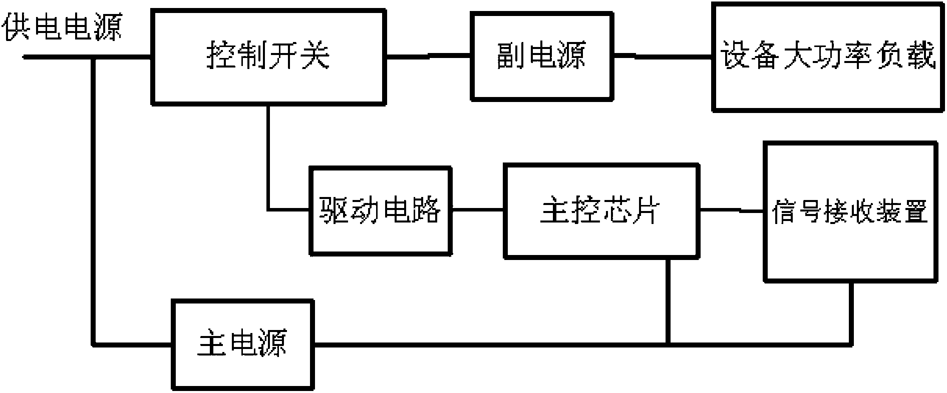
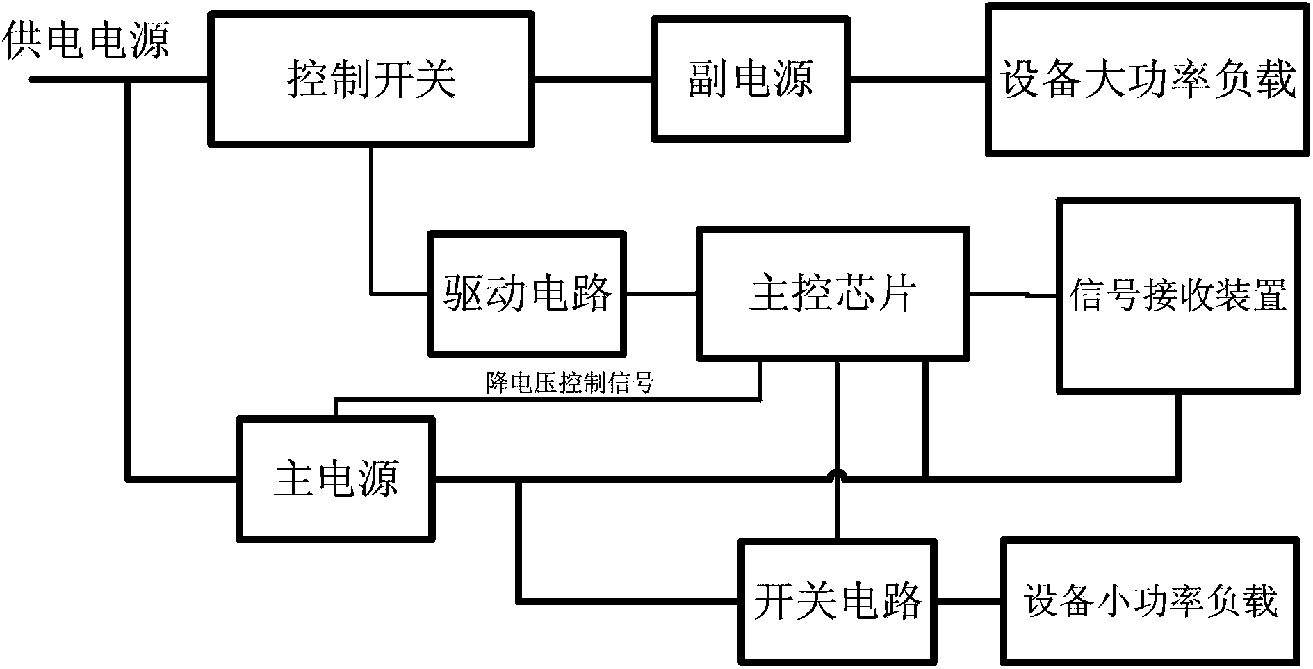
[0041] When the quasi-zero power consumption standby control circuit device of the present invention is applied, power-consuming loads such as electrical equipment are divided into three parts: a high-power load part, a low-power load part, and the main control chip of the control circuit device itself, and in the In the above control circuit device, two power supplies are designed to supply power to these three parts separately; wherein the high-power load part is powered by the auxiliary power supply, and the auxiliary power supply is controlled by a switch, and the auxiliary power supply is not powered during standby, so that the high-power load part is powered off; The low-power load part and the main control chip are powered by the main power supply, and the control circuit device is also provided with a signal receiving device, and is also powered by the main power supply; wherein the power supply of the low-power load circuit is controlled by a switch, and the power is cu...

Embodiment 2

[0061] A control method for a quasi-zero power consumption standby control circuit device, including a booting step and a standby step;

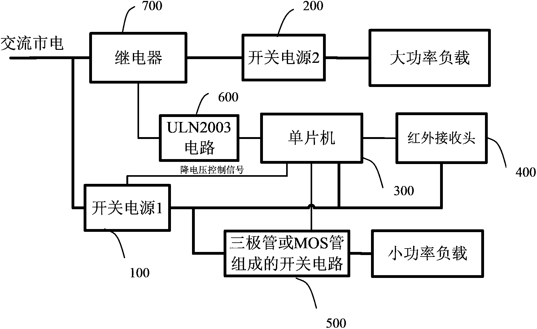
[0062] The power-on step is: when the signal receiving device receives the wake-up code of the power-on signal, trigger the main control chip to exit the low power consumption mode, so that the main control chip receives the power-on signal, and controls the switch circuit switch turn on, the low-power load circuit of the device is energized, and then the main control chip controls the secondary power control switch to be turned on, so that the secondary power supply is energized, and then the high-power load circuit of the device is energized, and then Then execute the boot action to enter the boot running state.

[0063] The standby step is: after entering the standby mode, the secondary power supply control switch is turned off, and the switch circuit is turned off at the same time, so that the connection between the low-power load circui...


PUM


Abstract

The invention discloses a quasi-zero power consumption standby control circuit device. The quasi-zero power consumption standby control circuit device is arranged between a power supply and an electrical device and comprises a main power supply, an auxiliary power supply and a main control chip. An input end of the main power supply is directly connected with the power supply, and an output end of the main power supply is connected to the main control chip and used for supplying power to the main control chip; an input end of the auxiliary power supply is connected to the power supply through a control switch, and an output end of the auxiliary power supply is connected with a load in the electrical device; a first control end of the main control chip is connected with the control switch and used for controlling the control switch to be turned on and off. The invention further relates to a control method applied to the control circuit device. Through the mode of independent power supply to a high-power load circuit, a small-specification power supply can serve as the main power supply, extremely high efficiency can be kept during a light load, the main power supply is extremely small in load during standby time, and accordingly ultra-low power consumption during the standby time is achieved.

Description

technical field [0001] The invention relates to a control circuit device of electrical equipment, in particular to a quasi-zero power consumption standby control circuit device and a control method. Background technique [0002] Many household appliances have a standby function, which consumes power during standby. Standby loss has always been a problem that cannot be ignored in electrical equipment. Power, this is what we call standby power consumption. The standby power consumption of existing electrical appliances may be only a few watts, but it causes a lot of waste of electric energy. [0003] The State Council launched the "Energy Conservation and Emission Reduction, National Action" in 2007. After the "Energy Conservation and Emission Reduction", the winning certification center took the lead in implementing the "1W Plan" across the country. The core content of the "1W Plan" is to reduce the standby power of circuit equipment. consumption. The national policy attac...

Claims


Application Information

Patent Timeline
IPC IPC(8): G05B19/04H02M7/217
CPCY02B70/16Y02B70/10
Inventor 周建建李发顺
Owner GREE ELECTRIC APPLIANCES INC
Why Eureka
Try Eureka