Automatic chip machine

A chip and automatic technology, applied in the direction of electrical components, inductance/transformer/magnet manufacturing, circuits, etc., can solve the problem of production accuracy and consistency affecting chip quality and consistency, work efficiency depends on work experience, quality and consistency Difficult to guarantee and other problems, to achieve the effect of eliminating potential safety hazards, reducing labor intensity, and improving consistency

Active Publication Date: 2016-02-10
青岛云路特变智能科技有限公司
View PDF5 Cites 0 Cited by
  • Summary
  • Abstract
  • Description
  • Claims
  • Application Information

AI Technical Summary

Problems solved by technology

[0004] It can be known from the above description that this manual chipping method has the following defects: 1. The efficiency of manual chipping is low, and the work efficiency is heavily dependent on work experience. On average, two skilled workers with half a year's work experience in this position, Only 2 silicon steel laminates can be coded per minute, and workers with no work experience are less efficient
2. The quality of manual chipping is affected by many factors such as the precision of the part and manual techniques, and its quality and consistency are difficult to guarantee
It can be seen from the above description that the thickness measurement standard of the manual chip is a manufactured workpiece. The manufacturing accuracy and consistency of this public part seriously affect the quality and consistency of the chip, and the degree of wear after a certain period of time is also directly affected. Affects the quality and consistency of the chip; since the thickness measurement method is measured according to the level of manpower, the sense of responsibility and operation method of the operator also directly affect the quality of the chip
3. The thickness measurement adopts the method of manual horizontal advancement, and the other hand needs to take back the extra silicon steel sheet, which may be several layers or one layer. Since the thickness of the silicon steel sheet is micron level and very sharp, it is easy to cut hands during this process. ,There are security risks

Method used


Image

  • Automatic chip machine
  • Automatic chip machine
  • Automatic chip machine

Examples


Embodiment Construction

[0037] The present invention will be described in detail below in conjunction with the accompanying drawings and embodiments.

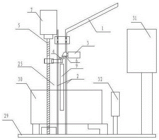
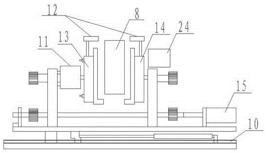
[0038] The technical solution of this embodiment is: an automatic chipping machine, a feeding part is arranged above the left side, a distributing part 25 is arranged under the left side, a glue part 31 is arranged above the right side, and a Collection part 32 is set, and shaping part 30 is set at its bottom; Said material distribution part 25 comprises the vertical guide rail 2 that is arranged up and down, and described shaping part 30 comprises the left and right clamping platform 12 that can move left and right along horizontal guide rail 10; Said vertical guide rail 2 is connected with the feeding part, and the left and right clamping platforms 12 can move to the front of the vertical guide rail 2, between the front and rear devices of the collecting part 32, and directly below the gluing part 31 from left to right.

[0039] The feeding part inc...


PUM


Abstract

The invention relates to an automatic sheet stacking machine, in particular to a machine capable of automatically stacking silicon steel sheets to silicon steel laminations with a certain thickness, and coiling and fixing through adhesive tape. The automatic sheet stacking machine is characterized in that a feeding part is arranged above the left side, a material distribution part is arranged below the left side, a gluing part is arranged above the right side, a collecting part is arranged at the middle part, and a sizing part is arranged on the lower part. According to the automatic sheet stacking machine provided by the invention, the silicon steel sheets can be automatically stacked to the silicon steel laminations with a certain thickness, and are coiled and fixed through the adhesive tape, six silicon steel laminations can be stacked by one machine in every minute, ten skilled workers can be replaced by one machine, so that production efficiency is effectively improved, and labor intensity of the worker is reduced; and furthermore, gaps and the thickness of the silicon steel laminations can be controlled by the machine, so that consistency of products is greatly improved, and potential safety hazards of manual measurement of the thickness of the silicon steel laminations can be removed.

Description

technical field [0001] The invention relates to an automatic stacking machine, in particular to a machine capable of automatically stacking silicon steel sheets into silicon steel laminations of a certain thickness, and wrapping and fixing them with adhesive tape. Background technique [0002] Dry-type three-phase reactors include iron cores and coils. The iron cores generally adopt a planar laminated structure. Therefore, according to the performance of the reactor, silicon steel sheets of corresponding thickness and size need to be coded into silicon steel laminates. In the prior art, manual methods are used to complete the work of stacking silicon steel sheets into silicon steel laminations. [0003] The manual chipping process generally includes the following steps: Step 1: Prepare a cube-shaped workpiece with the same height as the thickness required by the silicon steel lamination, and fix it on a horizontal operating table as a thickness measurement workpiece. Step 2...

Claims


Application Information

Patent Timeline
Patent Type & Authority Patents(China)
IPC IPC(8): H01F41/02
Inventor 苏新轩杨乃涛张秀宝
Owner 青岛云路特变智能科技有限公司
Why Eureka
Try Eureka