Method for controlling permanent-magnet synchronous motor in full-speed range without position sensors in surface-mounted mode

A technology of permanent magnet synchronous motor and control method, which is applied in the fields of motor generator control, AC motor control, electronic commutation motor control, etc., and can solve the problem of complex algorithm, difficult signal processing, and decreased estimation accuracy of pulse vibration high-frequency injection method And other issues

Active Publication Date: 2013-12-04
XI AN JIAOTONG UNIV
View PDF3 Cites 26 Cited by
  • Summary
  • Abstract
  • Description
  • Claims
  • Application Information

AI Technical Summary

Problems solved by technology

[0005] However, the pulse vibration high-frequency injection method has complex algorithms, difficult signal processing, and high requirements for hardware processing capabilities, so it is difficult to implement
Moreover, when the speed rises to the medium-high speed range, the delay of the position and speed generated by the filter will affect the dynamic performance of the speed control, and tracking failure may occur, an

Method used


Image

  • Method for controlling permanent-magnet synchronous motor in full-speed range without position sensors in surface-mounted mode
  • Method for controlling permanent-magnet synchronous motor in full-speed range without position sensors in surface-mounted mode
  • Method for controlling permanent-magnet synchronous motor in full-speed range without position sensors in surface-mounted mode

Examples


Embodiment Construction

[0042] The present invention will be described in detail below in conjunction with the accompanying drawings.

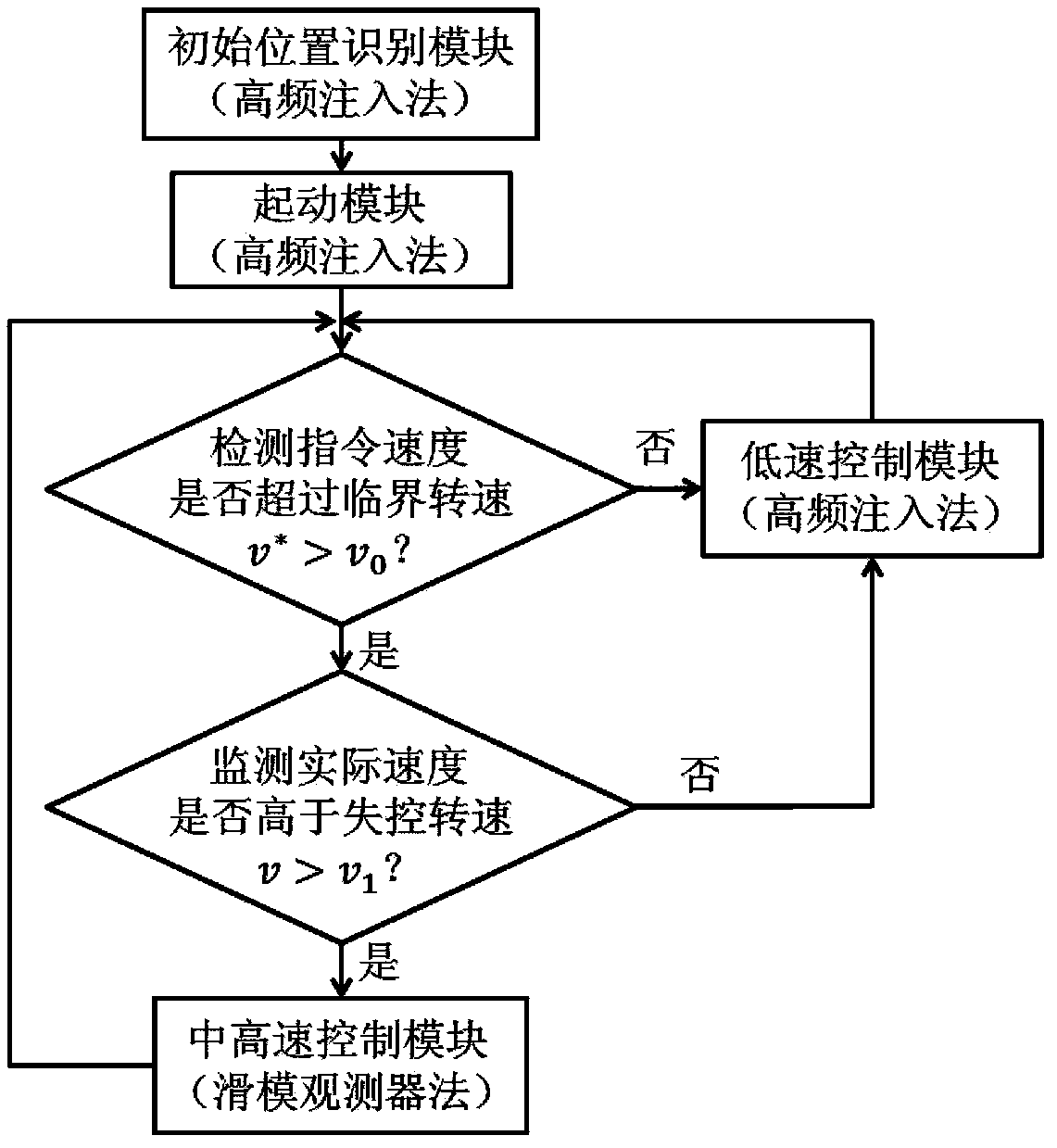
[0043] A full-speed range sensorless control method for surface-mounted permanent magnet synchronous motors, comprising the following steps, see figure 1 Shown:

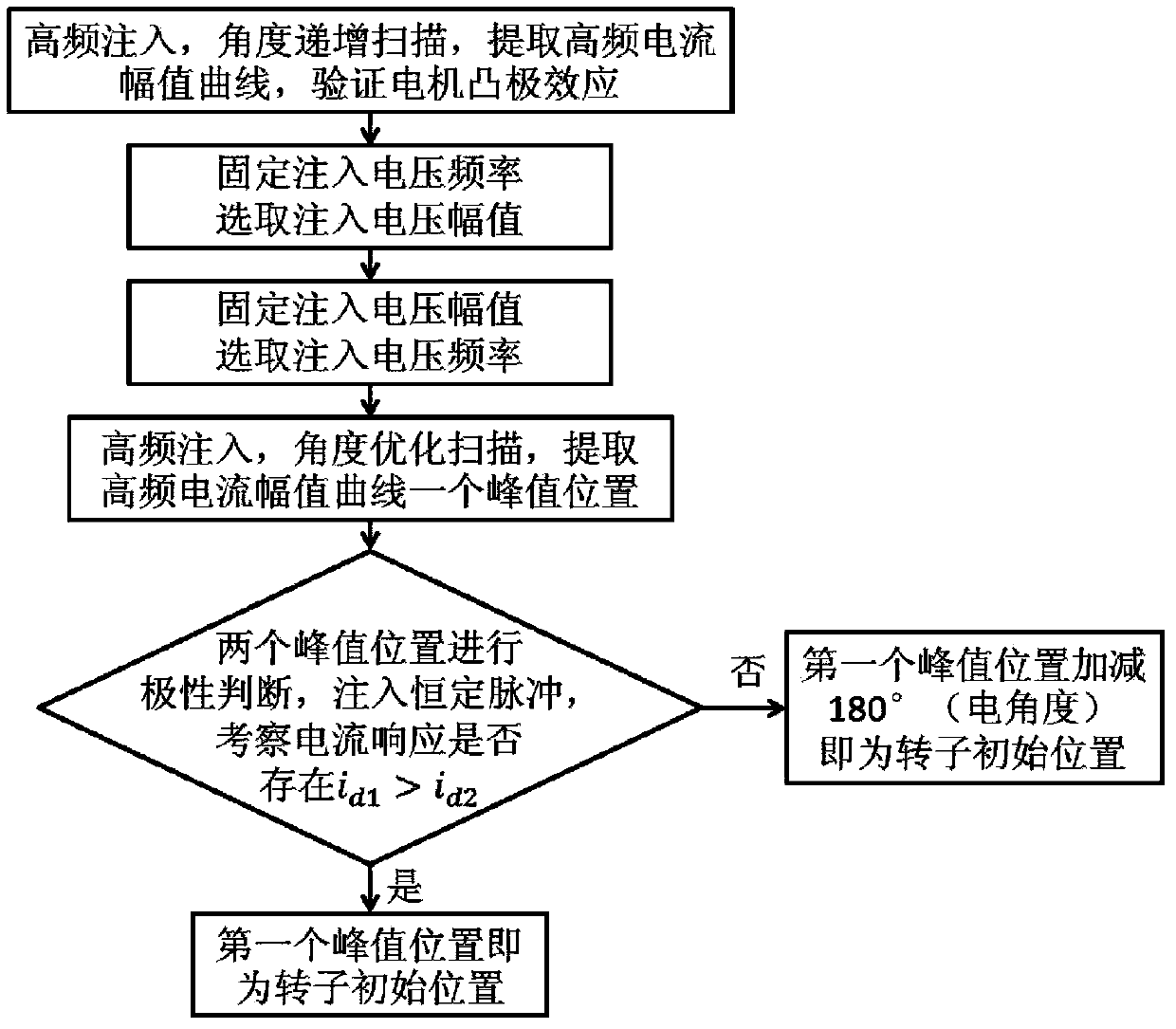
[0044] (1) When the motor is stationary, estimate the coordinate system towards the two-phase rotation of the motor rotor of Inject pulse vibration high-frequency voltage signal on the axis exist No signal is injected on the axis, where, is the amplitude of injected high-frequency pulse vibration voltage, ω h In order to inject the angular frequency of pulsed high-frequency voltage, the injection angle is scanned within the range of 360° electrical angle, and the coordinate system is estimated according to the two-phase rotation. The initial position of the motor rotor is obtained by using the high-frequency feedback current amplitude curve of the shaft and the nonlinear magnetization characteri...


PUM


Abstract

The invention discloses a method for controlling a permanent-magnet synchronous motor in a full-speed range without position sensors in a surface-mounted mode. The method includes firstly, injecting pulsating high-frequency voltage signals into an axis of a two-phase rotation estimation coordinate system, scanning the permanent-magnet synchronous motor within a 360-degree electric injection angle range and recognizing the initial position of the permanent-magnet synchronous motor according to high-frequency feedback currents of the axis; secondly, tracking the position of the permanent-magnet synchronous motor in real time according to the high-frequency feedback currents of the axis; thirdly, controlling the permanent-magnet synchronous motor in a medium and high-speed range and a low-speed range without the position sensors by a pulsating high-frequency injection process and a sliding-mode observer process and selecting control processes according to an instruction speed and an actual speed so as to control the permanent-magnet synchronous motor in the full-speed range without the position sensors. The method has the advantages that the two control processes supplement each other, so that the control performance can be improved to a certain extent as compared with the control performance when each control process is used individually, the dependence of the sliding-mode observer process on parameters of the motor is cast off, the influence of the high-frequency injection process on a sliding-mode observer and original control for the permanent-magnet synchronous motor is eliminated, and a perfect strategy for controlling the permanent-magnet synchronous motor in the full-speed range without the position sensors in the surface-mounted mode is provided.

Description

technical field [0001] The invention relates to the field of vector control of permanent magnet synchronous motors, in particular to a position sensorless control method in the full speed range of a surface-mounted permanent magnet synchronous motor. Background technique [0002] The permanent magnet synchronous motor has been more and more widely used because of its high power factor and outstanding load capacity, and its development direction has also changed from ordinary small and medium-sized to miniaturization and high power. The photoelectric encoder as a position detection element is a conventional configuration for precise control of permanent magnet synchronous motors, but the existence of encoders increases the connection and interface circuits between the motor and its control system, making the system susceptible to interference and affecting the reliability of the entire system Sex, which limits the application range of permanent magnet synchronous motors; in a...

Claims


Application Information

Patent Timeline
IPC IPC(8): H02P21/00H02P21/13H02P21/14H02P25/02
Inventor 梅雪松孔凡峰张迎庆陶涛许睦旬刘善慧
Owner XI AN JIAOTONG UNIV
Why Eureka
Try Eureka