Multiphase clock generation circuit

A multi-phase clock and circuit generation technology, which is applied in the electronic field, can solve the problems affecting the accuracy of the circuit and the phase uniformity of the output clock, and achieve the effect of high reliability, simple structure and uniform distribution of phase difference

Inactive Publication Date: 2013-12-04
UNIV OF ELECTRONICS SCI & TECH OF CHINA
View PDF3 Cites 12 Cited by
  • Summary
  • Abstract
  • Description
  • Claims
  • Application Information

AI Technical Summary

Problems solved by technology

[0023] It can be seen that when r=N / 2, the maximum integral nonlinearity is T step ×N / 4, and the large integral nonlinearity affects the uniformity of the output clock phase, which in turn affects the subsequent circuit accuracy

Method used


Image

  • Multiphase clock generation circuit
  • Multiphase clock generation circuit
  • Multiphase clock generation circuit

Examples


Embodiment Construction

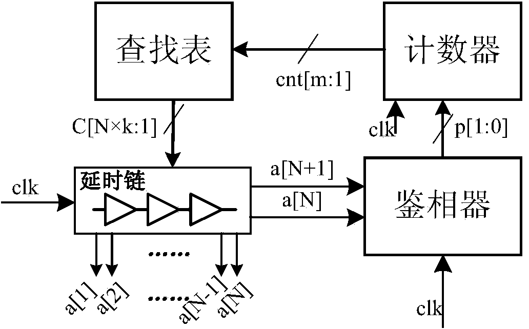
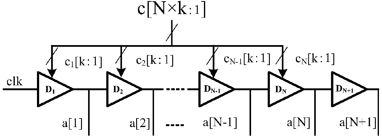
[0040] A multi-phase clock generation circuit, its structure is as follows figure 1 , 2 As shown, it includes a delay chain, a phase detector, a counter and a look-up table module; the delay chain is formed by (N+1) delay units connected in series, wherein the input terminal of the first delay unit As the input terminal of the entire delay chain, it is connected to a fixed-frequency reference clock clk; N k-bit control signals c[k:1] are recorded as c[n×k:1], n=1,2,…,N,N is a natural number, where the first k-bit control signal c 1 [k:1] controls the first delay unit, the second k-bit control signal c 2 [k:1] controls the second delay unit, the nth k-bit control signal c n [k:1] Control the nth delay unit until the Nth k-bit control signal c N [k:1] controls the Nth delay unit; the first N delay units are respectively in the corresponding k-bit control signal c n Under the control of [k:1], corresponding N clocks a[1]~a[N] with the same frequency and different phases are ...


PUM


Abstract

The invention discloses a multiphase clock generation circuit, and belongs to the technical field of electronics. The multiphase clock generation circuit comprises a delay chain, a phase discriminator, a counter and a lookup table module. The phase discriminator judges whether delay of the delay chain is equal to a reference clock period or not, and the delay of delay units of the delay chain is adjusted according to output results of the phase discriminator, so that the delay of the delay chain is equal to the reference clock period. In the adjusting process and N delay units, the delay of k delay units is smaller than an ideal value, the delay of N-k delay units is larger than the ideal value, and both N and k are integers. The delay units are divided into 2*min [k, (N-k)] +1 groups, and the difference of control codes of the delay units in adjacent groups is 1, so that an optimized linearity result is obtained. The multiphase clock generation circuit has the advantages of simple structure, high reliability, low differential nonlinearity and integral nonlinearity and the like.

Description

technical field [0001] The invention belongs to the field of electronic technology and relates to a clock generation circuit, in particular to a clock generation circuit capable of generating a plurality of clock outputs with uniform phase difference distribution under the excitation of a fixed-frequency reference clock. Background technique [0002] With the continuous improvement of VLSI processing technology, SoC chips contain more and more transistors. In a SoC designed with synchronous digital circuits, the synchronous clock usually has to drive a large number of transistors and interconnection lines to reach the functional modules connected to it in different positions, so that the delay of the clock reaching the functional modules in different positions in the circuit is inconsistent, which may cause As a result, the clock cannot ensure that all functional modules work synchronously, resulting in circuit logic errors. Therefore, the generation and distribution of on-c...

Claims


Application Information

Patent Timeline
Patent Type & Authority Applications(China)
IPC IPC(8): H03K3/02
Inventor 甄少伟甘武兵夏婷婷陈静波罗萍贺雅娟张波
Owner UNIV OF ELECTRONICS SCI & TECH OF CHINA
Why Eureka
Try Eureka