
Pulse signal generation circuit and method, clock generation module and display device

A pulse signal and circuit generation technology, applied in pulse generation, delay line pulse generation, pulse technology, etc., can solve the problem of high difficulty in circuit design of pulse signal groups, achieve uniform phase difference distribution, easy integration, and high working limit frequency Effect

Pending Publication Date: 2020-07-28
BOE TECH GRP CO LTD
View PDF6 Cites 0 Cited by
  • Summary
  • Abstract
  • Description
  • Claims
  • Application Information

AI Technical Summary

Problems solved by technology

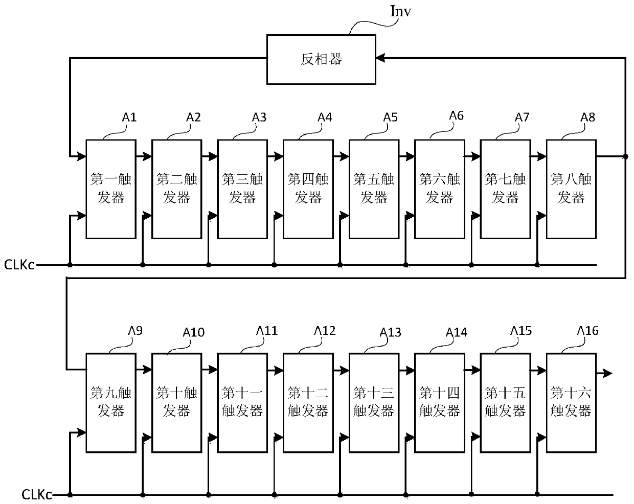
[0003] The main purpose of the present invention is to provide a pulse signal generation circuit, method, clock generation module and display device to solve the problem of high difficulty in circuit design for generating a pulse signal group with uniform phase distribution in the prior art

Method used


Image

  • Pulse signal generation circuit and method, clock generation module and display device
  • Pulse signal generation circuit and method, clock generation module and display device
  • Pulse signal generation circuit and method, clock generation module and display device

Examples


Embodiment Construction

[0027] The following will clearly and completely describe the technical solutions in the embodiments of the present invention with reference to the accompanying drawings in the embodiments of the present invention. Obviously, the described embodiments are only some, not all, embodiments of the present invention. Based on the embodiments of the present invention, all other embodiments obtained by persons of ordinary skill in the art without making creative efforts belong to the protection scope of the present invention.

[0028] The transistors used in all embodiments of the present invention may be triodes, thin film transistors or field effect transistors or other devices with the same characteristics. In the embodiment of the present invention, in order to distinguish the two poles of the transistor except the control pole, one pole is called the first pole, and the other pole is called the second pole.

[0029] In actual operation, when the transistor is a triode, the contr...


PUM


Abstract

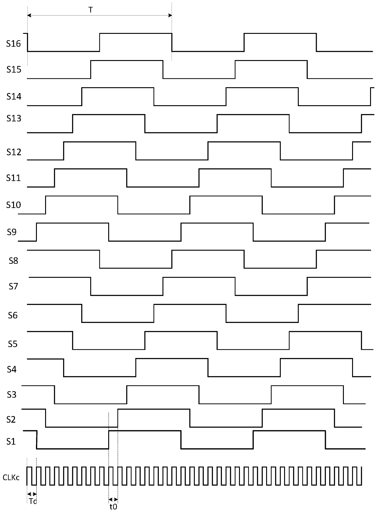
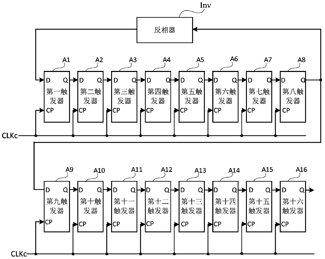
The invention provides a pulse signal generation circuit and method, a clock generation module and a display device. The pulse signal generation circuit comprises a phase inverter and 2N triggers, wherein N is a positive integer; the input end of the phase inverter is electrically connected with the signal output end of the Nth trigger, and the output end of the phase inverter is electrically connected with the trigger end of the first trigger; the signal output end of the nth trigger is electrically connected with the trigger end of the (n+1)th trigger, and n is a positive integer smaller than 2N; clock signal input ends of the 2N triggers are electrically connected with a control clock signal end; the control clock signal end is used for providing a control clock signal; and the triggeris used for controlling a signal accessed to the trigger end of the trigger to be transmitted to the signal output end of the trigger under the control of the control clock signal. According to the invention, pulse signal group output can be realized, so that phase difference distribution between adjacent pulse signals is uniform, and no extra phase jitter exists.

Description

technical field [0001] The invention relates to the technical field of pulse signal generation, in particular to a pulse signal generation circuit, method, clock generation module and display device. Background technique [0002] With the rapid development of electronic technology, modern electronic technology has higher and higher requirements on pulse timing. Phase jitter or fixed delay between pulse signals will cause electronic failure or system downtime. At present, the pulse signal group with uniform phase distribution needs to be generated using a phase locked loop (PLL). PLL is a digital-analog hybrid circuit. Not only is it difficult to design, but it needs to be designed from the bottom layer. Not suitable for rapid iteration of current products. Contents of the invention [0003] The main purpose of the present invention is to provide a pulse signal generating circuit, method, clock generating module and display device, which solves the problem of high difficul...

Claims


Application Information

Patent Timeline
Patent Type & Authority Applications(China)
IPC IPC(8): H03K3/013H03K3/86G09G5/00
CPCH03K3/013H03K3/86G09G5/00
Inventor 冯洁魏祥野李鑫
Owner BOE TECH GRP CO LTD
Learn More