Optical burst add drop multiplexer
A technology of add-drop multiplexer and optical burst, which is applied in the field of communication, can solve the problems of high cost of OBADM, and achieve the effect of solving high cost and reducing cost
- Summary
- Abstract
- Description
- Claims
- Application Information
AI Technical Summary
Problems solved by technology
Method used
Image

Examples
Embodiment 1
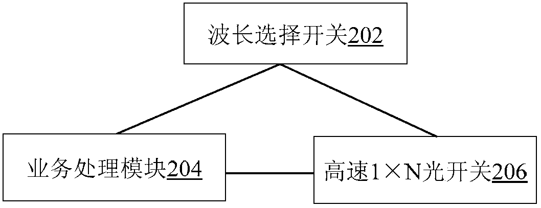
[0029] The embodiment of the present invention provides an OBADM. figure 2 is a structural block diagram of the OBADM according to Embodiment 1 of the present invention, such as figure 2 As shown, the OBADM includes: a wavelength selective switch 202, which is used to separate the optical signal from the line receiving optical fiber according to the wavelength; a service processing module 204, which is used to determine the wavelength of the optical signal to be received according to the optical signal separated by the wavelength selective switch; The high-speed 1×N optical switch 206 is coupled to the wavelength selective switch 202 and the service processing module 204, and is used to transmit the optical signal having the determined wavelength among the optical signals separated by the wavelength selective switch 202 under the control of the service processing module 204 to the business processing module 204.
[0030] In this embodiment, the wavelength selective switch a...
Embodiment 2
[0041] This embodiment provides a method for realizing OBADM by using a wavelength selective switch and a single high-speed optical switch. The implementation of this embodiment will be described in detail below.
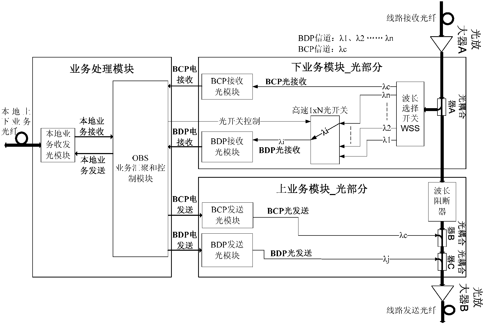
[0042] image 3 is a structural block diagram of the OBADM according to Embodiment 2 of the present invention, such as image 3 As shown, the OBADM includes the following four parts:
[0043] 1) Optical amplifier part
[0044] This part includes optical amplifier A (corresponding to the first optical amplifier) and optical amplifier B (corresponding to the second optical amplifier), which are respectively used to amplify the light from the line receiving fiber and the optical signal sent to the line sending fiber. Optical amplifier A and optical amplifier B can be ordinary continuous optical amplifiers, but not necessarily burst optical amplifiers.
[0045] 2) The optical part of the lower business module (corresponding to the lower business module)
[0046] ...
Embodiment 3
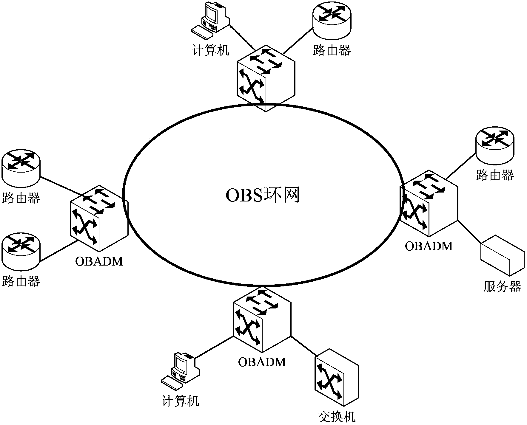
[0056] Figure 5 is a schematic diagram of an OBS ring network according to an embodiment of the present invention, such as Figure 4 As shown, this embodiment provides an OBS ring network composed of four OBADM nodes. In this implementation, the optical line contains 5 wavelengths in total: λc and λ1 to λ4, where λc is the BCP channel for the four nodes to send and receive BCP; λ1 is the BDP transmission channel of node 1, and λ2 is the BDP transmission channel of node 2 , λ3 is the BDP sending channel of node 3, and λ4 is the BDP sending channel of node 4. Image 6 It is a schematic diagram of node 1 according to Embodiment 3 of the present invention. The structures of other nodes and node 1 are similar to those of node 1 and will not be repeated here.
[0057] Each node on the ring network can communicate with the other three nodes. In this embodiment, the OBADM node 1 is taken as an example to describe the service processing process of each node.
[0058] Node 1 broadc...
PUM
 Abstract
Description
Claims
Application Information