
Yoke assembly for moving iron loudspeakers or receivers

A loudspeaker and receiver technology, which is applied in the fields of electroacoustics and micromechanics, can solve the problems of restricting the development of related moving iron speakers and receivers, complicating the manufacturing process, and weakening the competitive advantage, so as to achieve simple manufacturing process and improve the magnetic circuit structure , The effect of reducing product cost

Active Publication Date: 2018-04-03
SUZHOU YICHUAN TECH CO LTD
View PDF3 Cites 0 Cited by
  • Summary
  • Abstract
  • Description
  • Claims
  • Application Information

AI Technical Summary

Problems solved by technology

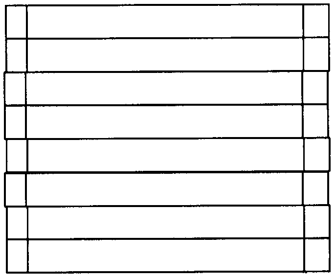
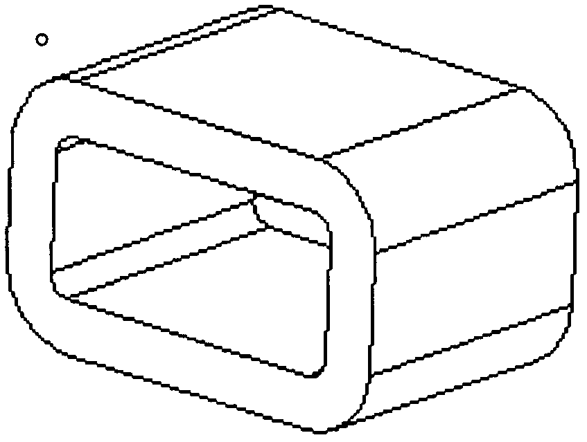
First of all, the shape characteristics of the existing two yoke devices limit the structure and volume of related products; secondly, the existing two methods generally have the disadvantages of complicated manufacturing process, large process variation, and high cost; further, stacking The resistance welding process used in the chip type will generate a lot of heat to destroy the internal magnetic circuit structure of the yoke and reduce its magnetic permeability, while the cast type yoke will leave many dense air gaps due to the characteristics of powder metallurgy. Destroy the internal magnetic circuit structure of the yoke, resulting in a decrease in its magnetic conductivity
Such structural, economic and functional deficiencies jointly restrict the development of related moving iron speakers and receivers, greatly weakening their competitive advantages

Method used


Image

  • Yoke assembly for moving iron loudspeakers or receivers
  • Yoke assembly for moving iron loudspeakers or receivers
  • Yoke assembly for moving iron loudspeakers or receivers

Examples


Embodiment Construction

[0022] The technical solution of the present invention will be further described below in conjunction with the accompanying drawings and a preferred embodiment.

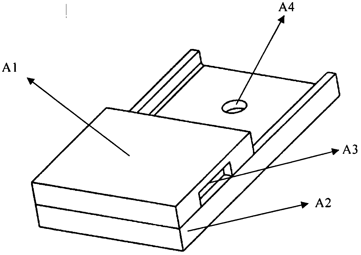
[0023] refer to Figure 3-5 , this embodiment relates to a yoke device B1 for a moving iron speaker or receiver, the yoke device B1 is a two-piece structure, comprising an upper part A1 and a lower part A2; the yoke device B1 has a Part A1 is a semi-box structure surrounded by four sides, and an opening groove A3 is placed on one side of the upper part; the lower part A2 of the yoke device B1 is also a semi-box structure surrounded by four sides structure, a through hole A4 is provided on the bottom surface of the lower part A2.

[0024] When in use, the upper part A1 and the lower part A2 of the yoke device B1 are aligned according to the edges and fixedly connected to form a yoke device B1 enclosed by the front end. In this embodiment, the combination of the upper part A1 and the lower part A2 of the yoke device ...


PUM


Abstract

Disclosed is a magnetic yoke apparatus for a moving-iron speaker or telephone receiver, with improved structure and manufacturing techniques. The apparatus comprises an upper and a lower portion, the two portions both being half-box structures enclosed on four sides. One side face of the upper portion of the magnetic yoke apparatus has an open groove, and the bottom face of the lower portion is provided with a through-hole. When the upper and lower portions of the magnetic yoke apparatus are assembled, the portions are aligned along the edges and are fixedly connected, enclosing the front end. The advantages of the present invention at least lie in: while guaranteeing the magnetic circuit of the moving-iron speaker or telephone receiver, the magnetic yoke apparatus enclosed by the upper and lower portions further being able to act as the housing thereof, greatly simplifying the structure of the product and not only reducing the product cost but also overcoming the inherent dimensional restrictions on a moving-iron speaker or telephone receiver, significantly reducing the external dimensions thereof, thus broadening the range of use thereof; and the improved structural design simplifying the construction techniques of the magnetic yoke apparatus, reducing costs, and the techniques involved damaging the magnetic conductivity less than traditional techniques, thus improving the structure of the magnetic circuit and increasing product performance.

Description

technical field [0001] The invention relates to a soft magnetic device for transmitting magnetic force lines, in particular to a magnetic yoke device used in a moving iron loudspeaker or receiver device, and belongs to the fields of electroacoustics and micromechanics. Background technique [0002] Most of the yoke devices used in the market for moving iron speakers or receivers are laminated and cast. Specifically, the lamination method first produces annular sheets with the characteristics of the yoke section by stamping, then stacks the sheets with mechanical assistance, and finally connects the stacked sheets by resistance welding to form a yoke; while the casting method requires First make the casting mold corresponding to the required yoke, and then cast the required yoke by powder metallurgy. First of all, the shape characteristics of the existing two yoke devices limit the structure and volume of related products; secondly, the existing two methods generally have th...

Claims


Application Information

Patent Timeline
Patent Type & Authority Patents(China)
IPC IPC(8): H04R11/02H04R11/06
CPCH04R11/02H04R11/06
Inventor 周巍
Owner SUZHOU YICHUAN TECH CO LTD
Learn More