
Robotic surgery micro-device for minimally invasive surgery
A technology of robotic surgery and minimally invasive surgery, applied in the field of medical devices, can solve the problems of inflexible operation of robotic surgery, and achieve the effect of flexible operation
- Summary
- Abstract
- Description
- Claims
- Application Information
AI Technical Summary
Problems solved by technology
Method used
Image

Examples
specific Embodiment approach 1
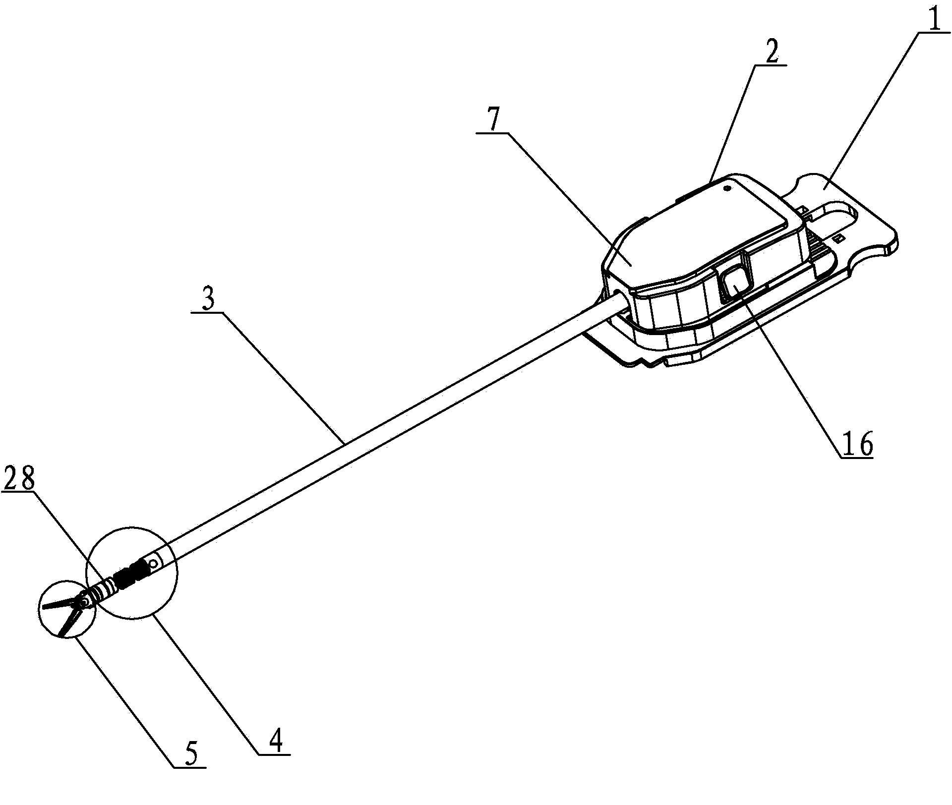
[0014] Specific implementation mode one: combine Figure 1-Figure 7 This embodiment is described. This embodiment includes a quick-change joint 1. The micro-instrument for surgical robotic surgery also includes a micro-instrument drive mechanism 2, a guide rod 3, a wrist mechanism 4, and an end effector 5. The quick-change joint 1, micro-instrument The driving mechanism 2, the guide rod 3, the wrist mechanism 4 and the end effector 5 are sequentially connected from right to left,
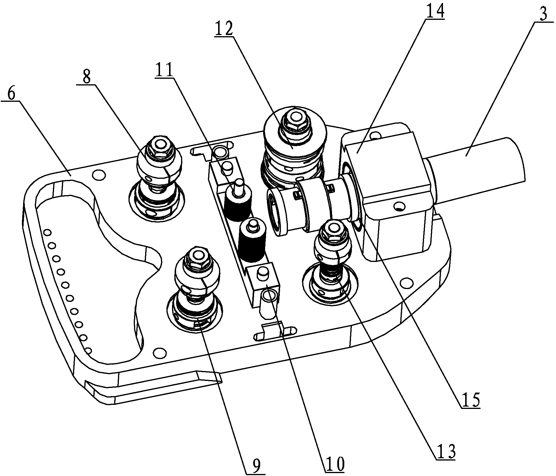
[0015] The micro-device drive mechanism 2 includes a base 6, an upper cover 7, a yaw drive wheel 8, a pitch drive wheel 9, a guide wheel bracket 10, a rotation drive wheel 12, a separation forceps drive wheel 13, a guide rod bracket 14, and a thin-walled bearing 15. The button 16 and a plurality of guide wheels 11, the yaw drive wheel 8 and the pitch drive wheel 9 are arranged side by side on the left side of the base 6, and the rotation drive wheel 12 and the separation clamp drive wheel 13 are arr...
specific Embodiment approach 2
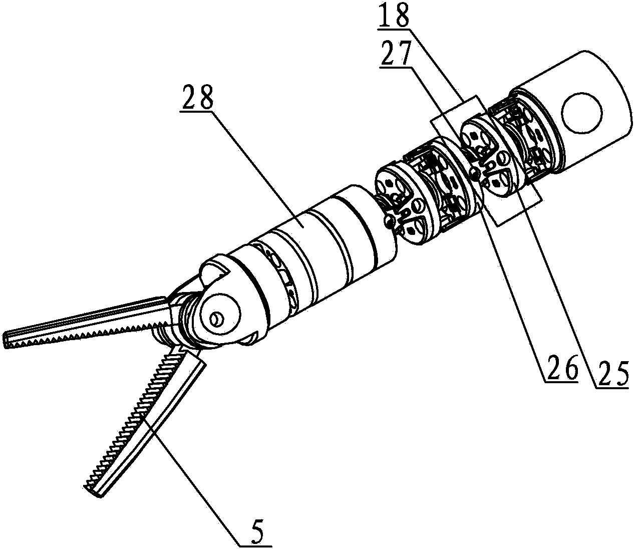
[0022] Specific implementation mode two: combination figure 2 and Figure 5 Describe this embodiment, the joint 18 of this embodiment includes the active joint 25, the driven joint 26 and the connecting rod 27, the active joint 25 and the driven joint 26 are arranged oppositely, the connecting rod 27 is arranged between the active joint 25 and the driven joint 26 between. In this way, adjacent active joints 25 and driven joints 26 are connected together by four peripheral threaded holes. There are square bosses and grooves on the opposite surfaces of the driven joint 26 and the active joint 25 respectively. The boss on the active joint 25 is embedded in the square groove of the driven joint 26, and the boss on the driven joint 26 is embedded in the square groove. Into the groove of the active joint 25, the active joint 25 and the driven joint 26 are screwed together by bolts to complete the assembly of the joint. Other compositions and connections are the same as in the fi...
specific Embodiment approach 3
[0023] Specific implementation mode three: combination figure 2 and Figure 5 Describe this embodiment, the joint 18 of this embodiment includes a connecting rod 27 rotatably disposed between the active joint 25 and the driven joint 26 . Such setting enables multiple joints 18 to move quickly and flexibly, which is convenient for operation and saves operation time. Other compositions and connections are the same as those in the second embodiment.
PUM
 Abstract
Description
Claims
Application Information