Disinfection device

A disinfection device and concentrated liquid technology, applied in medical science, diagnosis, endoscopy, etc., can solve the problems of concentrated liquid overflow, liquid flow disorder, complex structure, etc., to prevent odor leakage, simple structure, and maintain the working environment Effect

Active Publication Date: 2015-12-23
FUJIFILM CORP
View PDF2 Cites 0 Cited by
  • Summary
  • Abstract
  • Description
  • Claims
  • Application Information

AI Technical Summary

Problems solved by technology

Therefore, it is necessary to install a mechanism for loading and unloading the tube in the cleaning tank, and the structure becomes complicated.
[0012] In addition, in Japanese Patent Application Laid-Open No. 2006-230493, if the bottle is inserted into the bottle mounting part, a large amount of concentrated liquid is injected forcibly at the same time as the closure part is broken, so there is a danger of the concentrated liquid overflowing from the bottle mounting part.
Moreover, even if the concentrated liquid does not reach the level of overflow, the concentrated liquid will collide with the blade or the expanding surface near the blade and bounce back a lot, causing the liquid flow to be disturbed, so the concentrated liquid cannot flow smoothly into the disinfectant tank

Method used


Image

  • Disinfection device
  • Disinfection device
  • Disinfection device

Examples


no. 1 approach

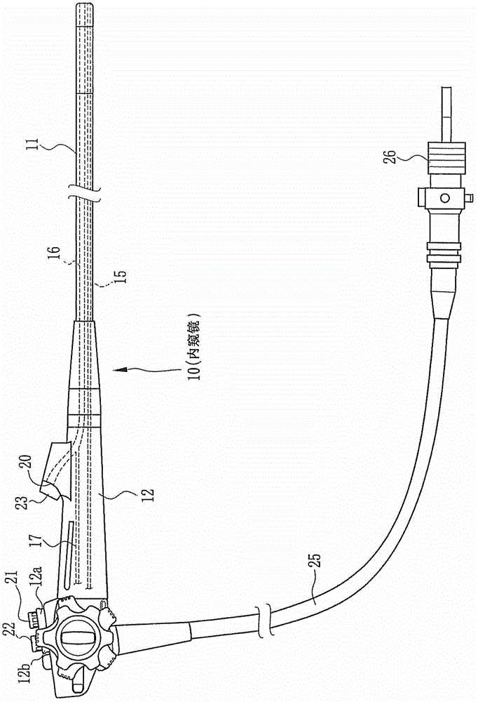
[0052] exist figure 1 Among them, the endoscope 10 has: an insertion section 11, which is inserted into a body cavity of a living body; and an operation section 12, which operates the insertion section 11. The insertion section 11 is in the shape of an elongated rod and has flexibility. The front end of the insertion section 11 is provided with: an illuminating unit for illuminating the inside of the body cavity; and an electronic imaging unit (not shown) for taking pictures of the inside of the body cavity. Air supply and water supply channels 15 and forceps channels 16 are arranged in the insertion section 11, and the ends of each channel are opened at the front end. The forceps channel 16 is connected to the suction channel 17 in the operating section 12 .

[0053] The operation section 12 is provided with a pliers mouth 20 connected to the pliers channel 16 , an air supply and water supply button 21 , and a suction button 22 . A pliers mouth cover 23 that is removed dur...

no. 2 approach

[0124] Next, refer to Figure 12 and Figure 13 , an embodiment in which a liquid discharge passage is formed in the cork opening portion of the bottle will be described. Looking at the bottle uncorked portion 110 from the side of the bottle unit 38, when the vertical line L1 passing through the center of the radial cross-section of the bottle uncorked portion 110 is at 0 o'clock, the center of the drain passage 110e is set so as to be at 6 o'clock. . In addition, the bottle unplugging part 110 is provided with the liquid discharge passage 110e, and Figure 5 and Figure 6 The examples shown have the same structure, and therefore the same structural parts are assigned only reference numerals and their descriptions are omitted. and, Figure 12 , Figure 13 and Figure 5 and Figure 6 Same, indicates bottle cleaning status.

[0125] The liquid discharge passage 110e is a passage for discharging the concentrated liquid to the concentrated liquid injection path 109 from t...


PUM


Abstract

The invention provides a disinfecting device. In a bottle housing a concentrated disinfecting liquid, an mouth is sealed with an obstruction portion. An opening portion of the bottle can enable the obstruction portion to be broken in the way that a part of the upper part of the obstruction portion is taken as a connecting portion to be reserved, and bends the obstruction portion from the connecting portion to the inner part of the bottle, thereby forming an outlet of the concentrated solution. After discharging the concentrated solution, the cleaning fluid from a nozzle is used for cleaning the inner part of the bottle. The nozzle is arranged at the position where the cleaning fluid and the obstruction portion are not collided and at the position above the water level of a returned cleaning fluid. The opening portion of the bottle has a blade portion for forming a cut on the obstruction portion. The concentrated solution from the cut is discharged by a liquid-discharging passage way formed on the external surface of the opening portion of the bottle.

Description

[0001] This application is a divisional application of a patent application with an application date of August 27, 2009, an application number of 200910168304.8, and an invention title of "disinfection device". technical field [0002] The present invention relates to a disinfection device suitable for disinfection of medical equipment such as an endoscope, and more specifically, to a disinfection device having a function of opening a bottle containing a concentrated solution of a disinfectant. Background technique [0003] Endoscopes are widely used for inspections and operations in body cavities of living bodies. The endoscope has an insertion section to be inserted into a body cavity, and an operation section to adjust the direction of the front end of the insertion section. The insertion section is in the shape of a flexible rod, and has various channels such as an electronic imaging unit for imaging the inside of the body cavity, and a forceps channel for inserting trea...

Claims


Application Information

Patent Timeline
Patent Type & Authority Patents(China)
IPC IPC(8): A61B1/12
Inventor 江尻铁平饭田孝之九贯义幸
Owner FUJIFILM CORP
Why Eureka
Try Eureka