Supercharge Your Innovation With Domain-Expert AI Agents!

Oval manhole ring machining tool

A manhole circle and oval-shaped technology, which is applied in the field of elliptical "manhole circle" processing tooling, can solve the problems of irregular ellipse shape, low efficiency, and increased manufacturing costs, so as to achieve good product quality, high production efficiency, The effect of simple structure

Inactive Publication Date: 2013-12-11
江苏维德锅炉有限公司
View PDF12 Cites 1 Cited by
  • Summary
  • Abstract
  • Description
  • Claims
  • Application Information

AI Technical Summary

Problems solved by technology

When making the elliptical "manhole ring", since the upper and lower pressure bearing surfaces of the press are flat, the force on the circumference of the steel ring is uneven during pressing, forming the two ends of the elliptical minor axis of the processed "manhole ring" There is a section that is flat, and the shape of the ellipse is not standardized. In order to standardize the pressed elliptical "manhole circle", a second manual finishing has to be done, which is time-consuming and labor-intensive, and the efficiency is not high.
In some factories, in order to avoid the manual second finishing process, a pressure head is added to the press, which can achieve the established processing purpose, but because the model of the press is different, the stroke of the press is also different, and the pressure needs to be adjusted. machine to make the necessary adjustments, thereby increasing the amount of material used, leading to higher manufacturing costs
In order to make the shape of the pressed oval "manhole circle" more standard, some factories directly make the upper and lower indenters into oval shapes. This has caused another problem, that is, the size of the oval "manhole circle" has changed. If there is a change, the upper and lower indenters also need to change accordingly, which requires the preparation of several indenters, which increases the processing cost
At the same time, the use of presses consumes electricity and the purchase cost is also high

Method used


Image

  • Oval manhole ring machining tool

Examples


Embodiment Construction

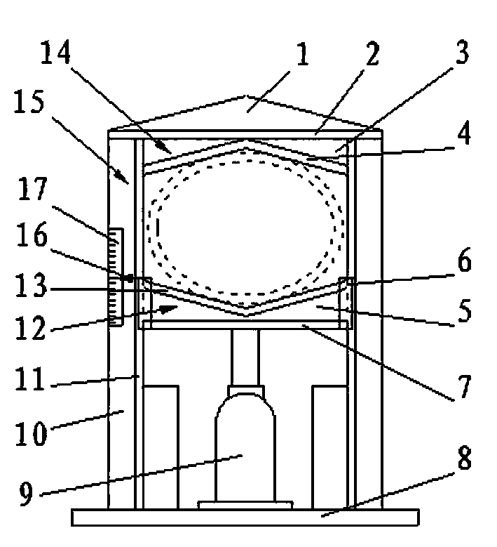
[0010] Such as figure 1 As shown, two elongated steel plates are connected in a T shape and welded together to form a T-shaped column 15. Two T-shaped columns 15 are welded and fixed on the two ends of the base plate 8, the upper pressing head 14 is welded and fixed on the top of the T-shaped column 15, and the lower pressing head 12 is clamped in the middle part of the T-shaped column 15 through the draw-in groove 6 and can be mounted along the T-shaped column. 15 moves up and down, the bottom of the oil top 9 is fixed on the middle part of the base plate 8, and the upper end connects the lower pressing head flat plate 7 on the lower pressing head 12.

[0011] Such as figure 1 As shown, the two ends of the top beam plate 2 in the upper pressure head 14 are welded and fixed on the T-shaped columns 15 on both sides and are perpendicular to the T-shaped columns 15; On the vertical plate 11, the upper end is welded and fixed on the roof beam plate 2, and the lower end is welded...


PUM


Abstract

The invention discloses an oval manhole ring machining tool, which relates to the technical field of tool equipment. The oval manhole ring machining tool is characterized in that two T-shaped vertical posts are fixed at the two ends of a bottom plate by welding; upper pressure heads are fixed on the upper parts of the T-shaped vertical posts by welding; lower pressure heads are clamped on the middle parts of the T-shaped vertical posts through necks, and can move upwards and downwards along the T-shaped vertical posts; the bottom of an oil ejector is fixedly arranged on the middle part of the bottom plate; the upper end of the oil ejector is connected with lower pressure head flat plates on the lower pressure heads; the lower pressure heads move upwards and downwards along the T-shaped vertical posts on both sides under the action of the oil ejector, and press a circular steel ring into an oval manhole ring. The tool has the advantages of simple structure, convenience in operation, low manufacturing cost, high production efficiency, good production quality and the like.

Description

technical field [0001] The invention relates to the technical field of tool equipment, in particular to an elliptical "manhole circle" processing tool. Background technique [0002] The elliptical "manhole circle" is a common part of industrial equipment, especially on the boiler, which is used more frequently. Sometimes a boiler needs to use several oval "manhole circles". The production method of the oval "manhole circle" is mainly to press with a press. When making the elliptical "manhole ring", since the upper and lower pressure bearing surfaces of the press are flat, the force on the circumference of the steel ring is uneven during pressing, which forms the two ends of the elliptical minor axis of the processed "manhole ring". One section is flat, and the elliptical shape is not standardized. In order to standardize the pressed elliptical "manhole circle", a second manual finishing has to be carried out, which is time-consuming and labor-intensive, and the efficiency i...

Claims


Application Information

Patent Timeline
Patent Type & Authority Applications(China)
IPC IPC(8): B21D53/16
Inventor 张垂德秦安军
Owner 江苏维德锅炉有限公司
Features
  • R&D
  • Intellectual Property
  • Life Sciences
  • Materials
  • Tech Scout
  • Unparalleled Data Quality
  • Higher Quality Content
  • 60% Fewer Hallucinations
Learn More