Ladle casting combined drainage device and method of manufacture and use

A ladle and drainage sand technology, which is applied to casting equipment, manufacturing tools, casting molten material containers, etc., can solve the problems of inconvenient production and use, complex structure of sand storage device, and high material consumption of shell, etc., to achieve novel conception, The effect of tight combination and low cost

Active Publication Date: 2016-07-06
周宇明
View PDF6 Cites 0 Cited by
  • Summary
  • Abstract
  • Description
  • Claims
  • Application Information

AI Technical Summary

Problems solved by technology

The disadvantages are that the structure of the sand storage device is complicated, the shell consumes a lot of materials, and it is inconvenient to manufacture and use; the nozzle is not filled with drainage sand, and the molten steel is poured into the ladle directly into the nozzle, and the molten steel is easy to condense in the nozzle, especially for molten steel refining. If the delay time is long, the molten steel in the nozzle is more likely to solidify, which seriously affects the pouring of molten steel

Method used


Image

  • Ladle casting combined drainage device and method of manufacture and use
  • Ladle casting combined drainage device and method of manufacture and use
  • Ladle casting combined drainage device and method of manufacture and use

Examples


Embodiment 1

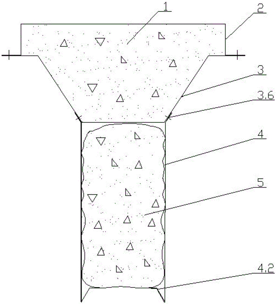
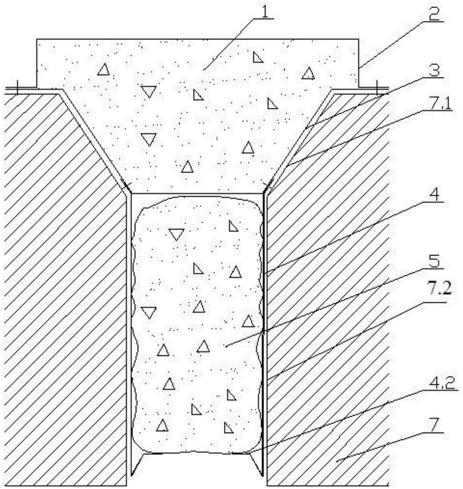
[0052] Depend on figure 1 , figure 2 It can be seen that the ladle casting combined drainage device is composed of a guide rod, a traction rope (not marked in the figure) and a drainage plug. The drainage plug is composed of the upper sand cylinder 2 and the lower sand cylinder 3, the fastening slats 4 and the lower drainage sand bag 5. The upper sand cylinder is a circular cylinder with a flat edge, and the diameter is larger than the upper mouth of the nozzle Diameter; the lower sand cylinder is a conical basin with flat sides, the diameter of the upper opening is equivalent to the inner diameter of the upper mouth of the nozzle, and the lower sand cylinder is consistent with the inner wall of the conical bucket of the nozzle; the diameter of the flat edge of the lower sand cylinder is the same as that of the upper sand cylinder. The outer diameters of the flat sides are equal, both of which are larger than the upper diameter of the nozzle. The upper sand cylinder is fixed...

Embodiment 2

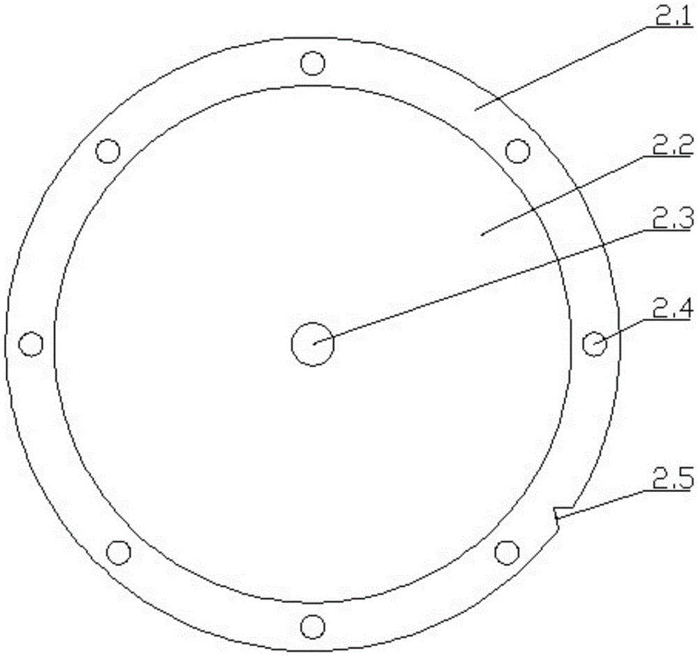
[0058] Depend on Figure 6 It can be seen that the center of the bottom 2.2 of the upper sand cylinder 2 is provided with a guide hole 2.3, the upper flat side 2.1 is provided with a through hole 2.4 and a gap 2.5, and the center of the lower sand cylinder 3 basin bottom 3.2 is correspondingly provided with a guide hole 3.3 and a lower flat side 3.1 Correspondingly, a lower through hole 3.4 and a lower notch 3.5 are arranged on the upper part, and a through hole (no serial number is marked) is arranged on the upper and lower sand cylinder walls. Drainage sand is placed in the soft metal mesh bag 6 that does not leak sand, and the metal mesh bag is placed in the synthetic cylinder of upper sand cylinder and lower sand cylinder. The weight of the cylinder is reduced, which is convenient for conveying; after the molten steel enters the ladle, the upper sand cylinder, the lower sand cylinder and the metal mesh bag are melted quickly, and the drainage sand is filled in the nozzle, ...


PUM


Abstract

The invention provides a combined drainage device for steel ladle casting and relates to a drainage device for starting casting from a ladle nozzle. The combined drainage device is characterized in that a drainage plug comprises an upper sand cylinder, a lower sand cylinder, a fastening lath and an underneath drainage sand bag, wherein the upper sand cylinder is a round cylinder, and the diameter of the upper sand cylinder is larger than that of an upper opening of a nozzle; the lower sand cylinder is a cone-shaped basin, the diameter of the upper end of the lower sand cylinder is equal to the inner diameter of the upper opening of the nozzle, the lower sand cylinder is matched with a cone-shaped body of the nozzle, the diameters of flat sides of edge holes of the lower sand cylinder and the upper sand cylinder are the same, the upper sand cylinder is fixed on the lower sand cylinder, and drainage sand is arranged in the upper sand cylinder; the fastening lath is arranged at the lower part of the lower sand cylinder, the underneath drainage sand bag is filled into a cavity formed by the surrounding of the fastening lath, and the fastening lath is extruded to the inner wall of the nozzle. The combined drainage device has the advantages that the conception is novel, the manufacturing process is easy, and the manufacturing cost is low; the drainage sand is arranged in the underneath drainage sand bag and a cylinder formed by the upper sand cylinder and the lower sand cylinder, respectively, the mass transfer is little, and the combined drainage device is light, convenient and flexible; the drainage sand is filled into the nozzle, so that the molten steel is prevented from being solidified, the casting is benefited, the loss caused when the casting cannot be carried out is reduced, and the steel-making production is benefited.

Description

technical field [0001] The invention belongs to a casting melt container, in particular to a drainage device for starting casting at a nozzle at the bottom of a ladle. Background technique [0002] Casting is an important process in steelmaking production. Successfully smelted molten steel is poured into ladles and cast directly or after refining. In the early days, the nozzle at the bottom of the ladle used a stopper rod to control and adjust the molten steel, and the pouring started smoothly. Because the movement of the stopper rod was difficult to control, the plug head was easy to fall off and was discarded. Most factories now use a sliding nozzle to intercept and control the casting of the ladle. In order to prevent the remaining steel, residue and other debris in the ladle from blocking the ladle nozzle (hereinafter referred to as the nozzle) and ensure smooth pouring, a special person is set up at the tapping station to throw it at the nozzle. Drainage sand in bags. ...

Claims


Application Information

Patent Timeline
Patent Type & Authority Patents(China)
IPC IPC(8): B22D41/44
Inventor 周宇明周宇辉
Owner 周宇明
Why Eureka
Try Eureka