A powder material transport vehicle

A technology for transporting vehicles and materials, which is applied in the field of powder material transporting vehicles. It can solve the problems of dual-power production cost and production difficulty, the remaining materials in the tank cannot be discharged, and occupy the effective volume, so as to enhance the practicality and driving stability. , enhance the structure and service life of the tank, and reduce the center of gravity of the tank

CN103434768BInactive Publication Date: 2015-10-14SHIYAN DAY SPECIAL PURPOSE VEHICLE TECH DEV
4 Cites 0 Cited by

Patent Information

Authority / Receiving Office
CN · China
Patent Type
Patents(China)
Current Assignee / Owner
Publication Date
2015-10-14
Estimated Expiration
Not applicable · inactive patent

Smart Images

  • Figure 1
    Figure 1
  • Figure 2
    Figure 2
  • Figure 3
    Figure 3
Patent Text Reader

Abstract

The invention discloses a powder and particle material transport vehicle which comprises an automobile chassis, a tank, an air compressor and an unloading control system, wherein fluidized beds which are arranged in a centralized way towards the center layer by layer are adopted as a plurality of branch bins of the tank; the powder and particle material transport vehicle has the structure that a plurality of layers of main guide plates which are gradually lowered towards the center are symmetrically arranged at the two sides of the length direction of each branch bin by taking a discharge hole as the center; diversion air holes are respectively arranged between air chambers under the plurality of layers of main guide plates and the main guide plates; the direction of the air flow of the diversion air holes are set towards the discharge hole; an air flow hole is formed in a clapboard between each air chamber and each diversion air hole; two side guide plates are symmetrically arranged at the two sides of each branch bin; the lower part of each side guide plate is provided with a lower layer diversion air hole; the direction of the air flow of the main guide plate and the side guide plate at the bottommost layer is set towards the center of the discharge hole, so that a rectangular region can be formed; particles or powder can be blown to the discharge hole and is collided with the air flow which is blown head-on, so that the residual material in the tank can be thoroughly removed. The powder and particle material transport vehicle is suitable for bulk grain particles and bulk cement powder.
Need to check novelty before this filing date? Find Prior Art

Description

technical field

[0001] The invention relates to a powder material transport vehicle suitable for bulk grain particles and bulk cement powder. Background technique

[0002] Powder material transport vehicle is also called bulk cement vehicle, which is composed of special vehicle chassis, bulk cement vehicle tank body, gas pipeline system, automatic unloading device and other parts. It is suitable for bulk transportation of fly ash, cement, lime powder, ore powder, granular alkali, and other powdery dry materials. It is mainly used in cement plants, cement warehouses, large construction sites and bulk grain transportation, which can save a lot of packaging materials and loading and unloading labor.

[0003] The tank body of the powder material truck is mainly composed of a tank body, a feed inlet, a fluidized bed, a discharge pipe, an air intake pipe and other accessories. There are two or three feeding ports on the top of the tank. The front and rear air chambers of the po...

Examples

Embodiment Construction

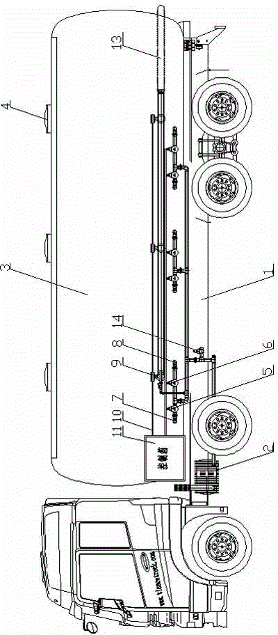
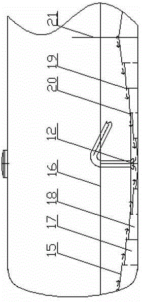
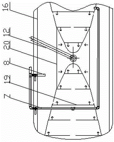
[0034] like figure 1 , figure 2 , image 3 and Figure 4 A kind of powder material transportation vehicle shown, comprises automobile chassis 1 and the tank body 3 that is installed on the automobile chassis, air compressor 2, unloading control system, and the tank body is divided into a plurality of compartments, each compartment There is a discharge port 12 in the center, and the fluidization system of the sub-bins adopts a layer-by-layer centripetal centralized fluidization form, that is, a layer-by-layer centripetal centralized fluidized bed;

[0035]The layer-by-layer centripetal centralized fluidized bed is centered on the discharge port 12, and multi-layer main flow guide plates 15 are symmetrically arranged on both sides along the length direction, and the main flow guide plates 15 are horizontal or have an inclination angle of 3-3 to the center. 5°, under the main deflector 15, it is divided into a high-level air chamber 17 and a bottom air chamber 18, and side de...