High-capacity photocatalytic wastewater degradation device for rigorously recovering titanium dioxide catalyst particles

A waste water degradation device, titanium dioxide technology, applied in chemical instruments and methods, water/sewage multi-stage treatment, water/sludge/sewage treatment, etc., can solve problems such as easy to pollute the inner wall of the quartz tube

Inactive Publication Date: 2013-12-11
李榕生
View PDF2 Cites 0 Cited by
  • Summary
  • Abstract
  • Description
  • Claims
  • Application Information

AI Technical Summary

Problems solved by technology

[0048] Based on the structure of the CN102260003A scheme, the electrodeless ultraviolet lamp is placed in the lumen of the quartz tube. In order to ensure the normal luminous work of the electrodeless ultraviolet lamp, the inner wall of the quartz tube must be kept clean to maintain the permeability to ultraviolet light. Moreover, based on similar light permeability requirements, the outer side of the lamp wall of the electrodeless ultraviolet lamp involved must also be kept clean; however, the structure of the CN102260003A scheme is difficult to avoid the problem of water inrush in the lumen area of ​​the quartz tube The so-called water inrush in this case refers to the unwelcome water in the reactor protruding into the lumen area of ​​the quartz tube; there are generally two reasons for the water inrush: one is the quartz tube The thermal expansion and contraction of the air in the cavity area leads to underpressure in the lumen area of ​​the quartz tube, and the second is that the air in the lumen area of ​​the quartz tube escapes and causes underpressure in the lumen area of ​​the quartz tube. In this way, driven by the relative positive pressure of the surrounding water body, The water in the reacto

Method used


Image

  • High-capacity photocatalytic wastewater degradation device for rigorously recovering titanium dioxide catalyst particles

Examples


Embodiment Construction

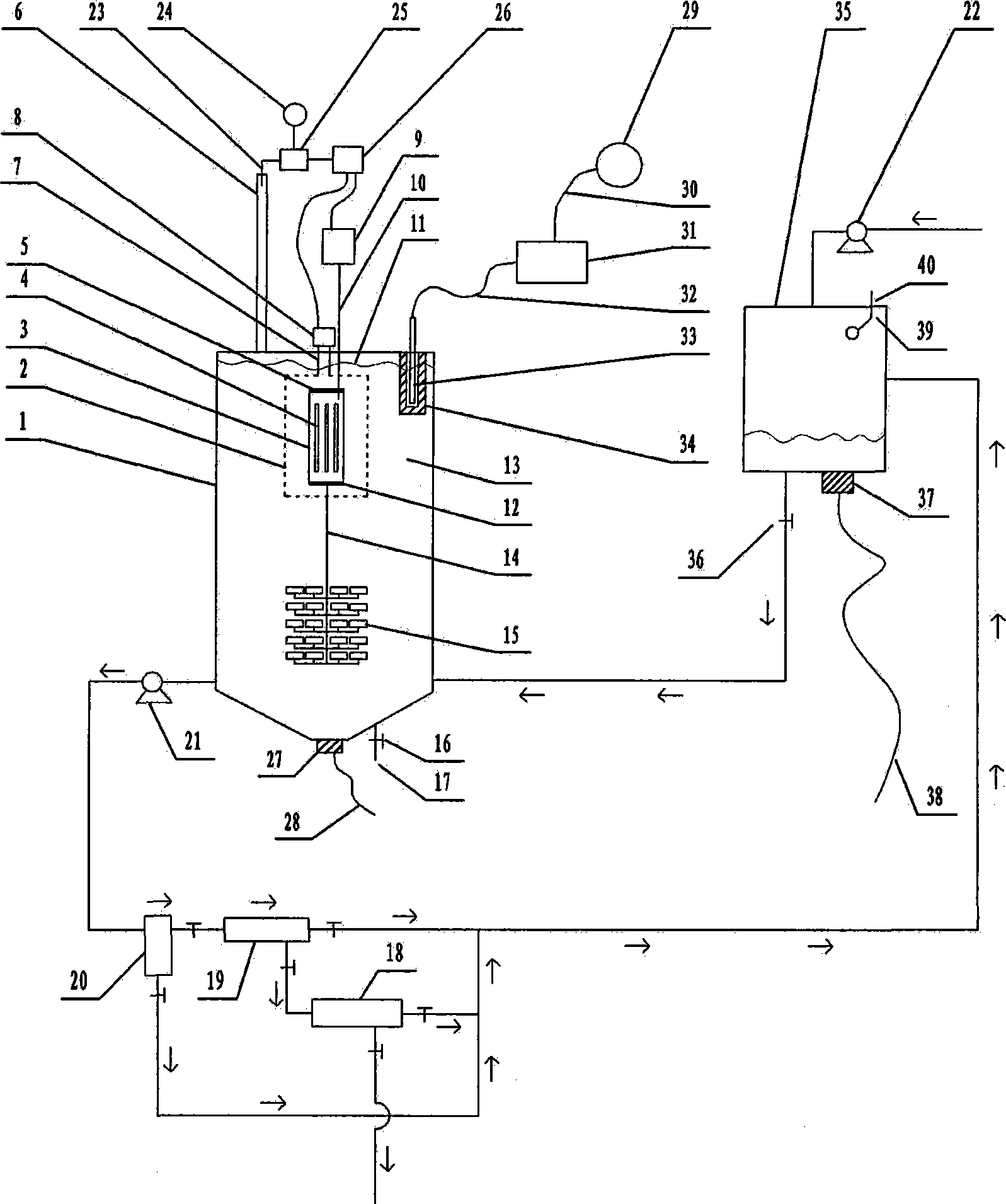
[0126] exist figure 1In the example of the present case shown, the structure of the device in this example includes a reactor 1, which is a hollow container. Prismatic, spherical or ellipsoidal, many microporous aeration heads 15 are installed in the lower area of ​​the inner chamber of the reactor 1, and the mark 15 only indicates the individual microporous aeration heads, and 15 only indicates the micropores The individual form of the aeration head, and, quartz tube 3, this quartz tube 3 is set up in the inner cavity position of described reactor, and the two ends of this quartz tube 3 are equipped with sealing cap 5,12, are respectively positioned at quartz tube 3 Both ends are provided with a ventilation interface, and the electrodeless ultraviolet lamp 4, the electrodeless ultraviolet lamp 4 is rod-shaped, ring-shaped, spherical, starfish-shaped or sea urchin-shaped, and the quantity of the electrodeless ultraviolet lamp 4 At least one, the number of at least one electro...


PUM


Abstract

The invention relates to a high-capacity photocatalytic wastewater degradation device for rigorously recovering titanium dioxide catalyst particles, and belongs to the technical field of wastewater treatment. The device aims at solving a serious of problems that the microwave energy is wasted, the single-tank wastewater treatment capacity is low, a bubble rising path is short, the oxygen supply concentration degree in a key area is insufficient, a catalyst particle interception link is weak, a degradation reaction endpoint is difficult to distinguish, a catalyst aggregator cannot be dissipated forcefully in situ, catalyst aggregation cannot be perceived immediately, preventive measures on water burst of a quartz cavity are insufficient, etc. in the prior art. A structure of the degradation device limits a microwave irradiation airspace, allows a reactor to be expanded greatly, facilitates reinforced supply of an air atmosphere in the key degradation reaction area, is suitable for intensively intercepting the catalyst particles, can dissipate the catalyst aggregator forcefully in situ, incidentally cleans a quartz tube ultrasonically, can turn off a relevant power supply automatically and immediately at the degradation endpoint, and can warn a trend of the catalyst aggregation.

Description

technical field [0001] The invention relates to a large-capacity photocatalytic waste water degradation device for strictly recovering titanium dioxide catalyst particles, and belongs to the technical field of CO2F waste water treatment. Background technique [0002] Microwave photocatalytic degradation treatment technology, as an effective harmless treatment technology for industrial wastewater containing organic pollutants, has attracted much attention in recent years. [0003] Regarding the microwave photocatalytic degradation technology, as an example, refer to the Chinese patent application with publication number CN102260003A. [0004] The Chinese patent application with the publication number CN102260003A uses microwaves as the excitation source to excite the electrodeless ultraviolet lamp to emit ultraviolet rays, and irradiates the suspension mixed with photocatalyst titanium dioxide inside the liquid. The electrodeless ultraviolet lamp is shrouded and protected by ...

Claims


Application Information

Patent Timeline
IPC IPC(8): C02F9/08
Inventor 李榕生
Owner 李榕生
Why Eureka
Try Eureka