In-situ chemical conditioning and vacuum preloading reduction method and conditioning device for landfill sludge

A chemical conditioning and sludge technology, applied in the direction of dewatering/drying/concentrating sludge treatment, etc., can solve the problems of low processing capacity, low efficiency, and difficulty in using landfill sludge, so as to reduce costs and avoid secondary pollution. Effect

Active Publication Date: 2014-07-23
ZHEJIANG UNIV
View PDF5 Cites 1 Cited by
  • Summary
  • Abstract
  • Description
  • Claims
  • Application Information

AI Technical Summary

Problems solved by technology

However, due to the consolidation coefficient of sludge (10 -5 cm 2 / s~10 -6 cm 2 / s) than soft soil, silt (10 -4 cm 2 / s) is 1-2 orders of magnitude lower, and the use of traditional vacuum preloading technology to directly treat sludge cannot achieve a good drainage reduction effect
The above shortcomings make it difficult to apply traditional vacuum preloading technology to the disposal of landfill sludge
[0007] The sludge secondary dehydration or deep dehydration technology developed by domestic scholars and companies is mainly used in sewage treatment plants to treat dewatered sludge, but its treatment capacity is small and the efficiency is low

Method used


Image

  • In-situ chemical conditioning and vacuum preloading reduction method and conditioning device for landfill sludge
  • In-situ chemical conditioning and vacuum preloading reduction method and conditioning device for landfill sludge
  • In-situ chemical conditioning and vacuum preloading reduction method and conditioning device for landfill sludge

Examples


Embodiment Construction

[0031] The present invention will be further described below in conjunction with the accompanying drawings and embodiments.

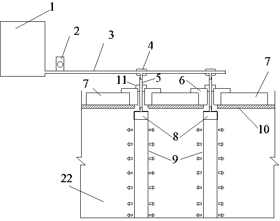
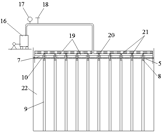
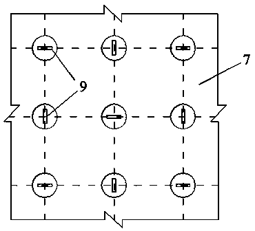
[0032] Such as figure 1 , image 3 , Figure 4 As shown, the bottom of the dissolving tank 1 of the present invention is connected to one end of the rubber tube 3 through the flow pump 2, and the other end of the rubber tube 3 is provided with a liquid outlet every 0.4m~0.6m, and each liquid outlet is respectively Install the perforated casing 4. Lay woven geotextiles 10 and high-strength foam boards 7 with multiple rows and columns of holes on the surface of the sludge landfill 22 from bottom to top, and connect plastic drainage board parts with the same structure to each hole casing 4; Each plastic drainage plate part comprises: plastic drainage plate 9, hand joint 8, connecting pipe 5 and stainless steel clip 12. One end of the connecting pipe 5 is connected to the nozzle of the hand joint 8, and the tank body of the hand joint 8 is connected to ...


PUM


Abstract

The invention discloses an in-situ chemical conditioning and vacuum preloading reduction method and a conditioning device for landfill sludge. The in-situ chemical conditioning and vacuum preloading reduction method comprises the following steps: firstly, adding an Fe<3+> conditioning agent in municipal sludge of a sludge landfill to improve the drainage consolidation characteristics of the municipal sludge; secondly, paving a sealing film on the surface of the sludge landfill, connecting a vacuum pump and applying negative pressure to drain and consolidate the conditioned sludge. The conditioning device is connected with a rubber hose at the bottom of a medicine dissolving box through a flow pump; liquid outlets are formed in the rubber hose at equal intervals; a tapping casing pipe is mounted at each liquid outlet; plastic draining plate assemblies with the same structure are respectively connected onto each tapping casing pipe. Woven geotextile and high-strength foam boards with a plurality of rows and columns of holes are sequentially paved on the surface of the sludge landfill from bottom to top; a plastic draining board penetrates through the woven geotextile through respective high-strength foam board holes and is inserted into the bottom of the sludge landfill. According to the in-situ chemical conditioning and vacuum preloading reduction method and the conditioning device disclosed by the invention, the in-situ reduction treatment on the landfill sludge is realized, work procedures such as excavation and transportation are not needed to be newly added and secondary pollution is avoided; meanwhile, the expenses are reduced.

Description

technical field [0001] The invention relates to solid waste treatment technology, in particular to an in-situ chemical conditioning and vacuum precompression reduction method and conditioning device for landfill sludge. Background technique [0002] Sludge is the solid sediment produced during municipal wastewater treatment. After the sludge is concentrated, digested and mechanically dehydrated in the sewage treatment plant, its moisture content on a wet basis is generally 80%-85%. In recent years, with the development of my country's social economy, sludge production has increased year by year. According to the China Environmental Yearbook, in 2012, the dewatered sludge produced by my country's urban sewage treatment plants was as high as 22 million tons, and it is still growing at a rate of 10% per year. At present, the main sludge disposal methods are landfill, composting, and incineration. Due to the high water content of mechanically dewatered sludge in my country, c...

Claims


Application Information

Patent Timeline
Patent Type & Authority Patents(China)
IPC IPC(8): C02F11/12C02F11/14
Inventor 詹良通占鑫杰林伟岸陈云敏
Owner ZHEJIANG UNIV
Why Eureka
Try Eureka