
Continuous circulation device and method for operation of assembling casing pipe

A circulation device and casing technology, applied in drilling equipment and methods, earthwork drilling, drilling equipment, etc., can solve problems such as difficult control of liquid pressure, long static time, resistance in casing running, etc., to reduce shrinkage diameter and collapse, reasonable and compact structure, and the effect of saving production costs

Active Publication Date: 2015-07-01
SINOPEC SHENGLI PETROLEUM ENG CO LTD DRILLING TECH RES INST +1
View PDF6 Cites 0 Cited by
  • Summary
  • Abstract
  • Description
  • Claims
  • Application Information

AI Technical Summary

Problems solved by technology

Problems caused by this method: First, the casing stays at the wellhead for too long, which increases the chance of casing sticking; second, manual hand-held pipeline injection, the liquid pressure is difficult to control, and personal injury accidents are prone to occur; third, mud circulation There are many operating links, and each cycle needs to connect and unload the well cleaning joint and kelly; Fourth, the casing operation takes a long time, and there are many statics in the middle, which will easily lead to serious resistance in casing running, improper casing running, blowout, and lost circulation Wait for complicated situations to happen
At present, in order to solve the above problems, there are individual casing running continuous circulation devices, but because of limited scope of application, or poor controllability, it is rarely useful in production

Method used


Image

  • Continuous circulation device and method for operation of assembling casing pipe
  • Continuous circulation device and method for operation of assembling casing pipe
  • Continuous circulation device and method for operation of assembling casing pipe

Examples


Embodiment Construction

[0031] The present invention will be described in detail below with reference to the drawings.

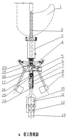
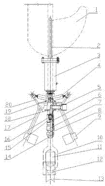
[0032] The continuous circulation device for casing running operation of the present invention includes a clamping system and a perfusion and circulation system.

[0033] The clamping system includes: a hanging ring 2, a vertical hydraulic cylinder 3, a combined connecting frame 19, a combined connecting head 18, an earring connecting liquid cylinder 4, a driving arm 20, a secondary grasping arm 17 and a secondary grasping card 9. The vertical hydraulic cylinder 3 is connected below the hanging ring 2, and the combined connecting frame 19 and the combined connecting head 18 are connected below the vertical hydraulic cylinder 3. The rodless ends of the two earrings connecting the hydraulic cylinder 4 are hingedly mounted on the combined connecting frame 19 back to back, There is a rod end connected to the driving arm 20, the other end of the driving arm 20 is fixedly connected to the sec...


PUM


Abstract

The invention discloses a continuous circulation device and method for operation of assembling a casing pipe. The device comprises a clamping system and a pouring and circulation system, wherein the clamping system is used for clamping the casing pipe to be assembled and controlling the lifting up and putting down of the whole set of device, a push-up force generated in the pouring and circulation process can be offset by gravity of a casing pipe column; the pouring and circulation system is used for pouring and circulating mud in the assembly process of the casing pipe. During continuous circulation, the casing pipe is filled with mud, pressure is increased, and a seal cup of the pouring and circulation system seals a set packer; mud pumped from a core pipe into the casing pipe reaches a shaft bottom and then upwards returns from an annular space between the outer part of a casing pipe wall and the inner part of a shaft, and the device starts mud circulating operation. The continuous circulation device has a reasonable and compact structure and has strong operability in use. During the operation of assembling the casing pipe, the device can prevent the casing pipe from being stuck, reduces shrinkage and collapse of a shaft wall, and can ensure the successful assembly of the casing pipe, so that the production cost is reduced.

Description

Technical field [0001] The invention belongs to the field of drilling engineering, and specifically relates to a continuous circulation device for casing running operation and a continuous circulation method for casing running. Background technique [0002] At present, in the drilling construction process, the process of grouting and establishing circulation during casing running is: sit the casing on the turntable, hold the mud pipeline with the elbow, grouting into the casing, and then wash Circulation of well joints and kelly. The problems caused by this method: First, the casing has been stationary at the wellhead for too long, which increases the chance of casing sticking; the second is manual hand-held pipeline infusion, the liquid pressure is difficult to control, and personal injury accidents are prone to occur; the third is mud circulation There are many operation links, each cycle needs to connect and unload the well flushing joint and the kelly; fourth, the casing ope...

Claims


Application Information

Patent Timeline
Patent Type & Authority Patents(China)
IPC IPC(8): E21B7/20
Inventor 张杨温林荣吴中华蔡文军
Owner SINOPEC SHENGLI PETROLEUM ENG CO LTD DRILLING TECH RES INST
Learn More