
Magnus effect rotor utilizing wind energy to generate electricity and produce pushing force

A technology of thrust and effect, applied in the field of Magnus effect rotors, can solve problems such as low power generation efficiency, limited Magnus force, limited utilization of wind energy, etc., and achieve high economical effects

Inactive Publication Date: 2013-12-11
NORTHWESTERN POLYTECHNICAL UNIV
View PDF12 Cites 4 Cited by
  • Summary
  • Abstract
  • Description
  • Claims
  • Application Information

AI Technical Summary

Problems solved by technology

The disadvantage of this device is that each radial rotating cylinder used to drive the horizontal rotating shaft to rotate and generate electricity cannot actively rotate around the central axis of its own cylinder, and the Magnus force provided is very limited, and the power generation efficiency at low wind speed may not be as good as the conventional level shaft wind turbine
However, the current Magnus effect rotor is still used alone in propulsion devices or wind power generation devices, the utilization rate of wind energy is limited, and the characteristics of the Magnus effect have not been fully utilized to maximize its effectiveness

Method used


Image

  • Magnus effect rotor utilizing wind energy to generate electricity and produce pushing force
  • Magnus effect rotor utilizing wind energy to generate electricity and produce pushing force
  • Magnus effect rotor utilizing wind energy to generate electricity and produce pushing force

Examples


Embodiment Construction

[0054] Describe the present invention below in conjunction with specific embodiment:

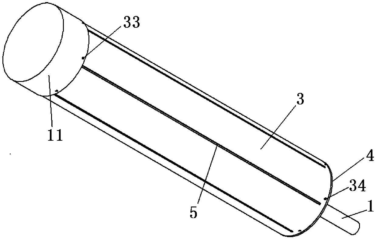
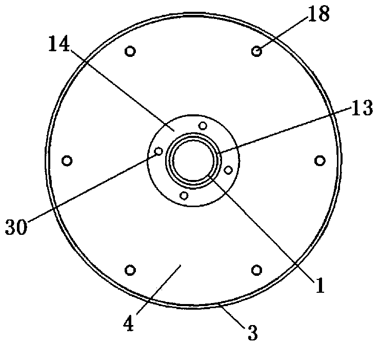
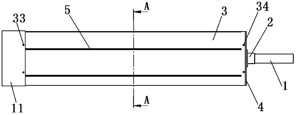
[0055] In this embodiment, the Magnus effect rotor utilizing wind energy for power generation and thrust generation includes a main shaft 1, a main rotor assembly, six sets of fan blade assemblies and a fan blade drive assembly.

[0056] The main drum assembly includes a main drum 3 , a main drum inner cover 4 and a main drum outer cover 7 . Refer to attached Figure 9 , the inner cover plate 4 of the main drum is connected and fixed to the main shaft 1 through the inner cover connector 2 of the main drum, and the outer cover plate 7 of the main drum is connected and fixed to the main shaft 1 through the outer cover connector 6 of the main drum. Refer to attached Figure 10 , the main shaft 1 is made of carbon fiber composite material, the shaft length is 1220mm, the outer diameter is 40mm, and the wall thickness is 3mm. There is a threaded through hole with a diameter of 6mm at a distance...


PUM


Abstract

The invention provides a Magnus effect rotor utilizing wind energy to generate electricity and produce pushing force. The Magnus effect rotor comprises a main rotating shaft, a main rotating barrel assembly, a plurality of sets of fan blade assemblies and a fan blade driving assembly. A plurality of fan blades evenly distributed around the circumference are installed inside a main rotating barrel, and due to the fact that fan blade folding and unfolding control driving gears are meshed with fan blade folding and unfolding control driven gears in a matched mode, a servo control motor can control all fan blades to stretch into or out of the main rotating barrel at the same time, wherein the fan blade folding and unfolding control driving gears are installed on a servo drive motor, and the fan blade folding and unfolding control driven gears are arranged on the end portions of all fan blade clamping sleeve rotating shafts. When the fan blades are located inside the main rotating barrel, the main rotating barrel is driven by an external motor to rotate, and then large pushing force is produced under the action of incoming flow. When the main rotating barrel is not needed to produce the pushing force, the fan blades stretch out of the main rotating barrel and are driven by wind power to drive the main rotating shaft to rotate so as to drive an external electric generator to generate electricity through the wind power. The rotor not only can serve as a propeller for providing the pushing force, but also can be used for generating the electricity when the pushing force does not need to be provided; the wind energy is fully utilized, and the Magnus effect rotor has high economical efficiency.

Description

technical field [0001] The invention belongs to the field of propulsion technology, in particular to a Magnus effect rotor that uses wind energy to generate electricity and generate thrust. Background technique [0002] The classic Magnus effect refers to a phenomenon in which a rotating cylinder moving in a viscous incompressible fluid is subjected to a lifting force. For example, when a soccer ball moves in the airflow, if the rotation direction of the upper spherical surface is in the same direction as the airflow, it will drive the airflow near the upper spherical surface to increase the flow velocity on the upper spherical surface and generate low pressure; The spherical surface creates high pressure, which creates lift. [0003] At present, the application of the Magnus effect is as the propulsion device of the ship and the rotor of wind power generation. [0004] Magnus effect rotors can be used as a propulsion system for ships due to strong offshore winds. Chinese...

Claims


Application Information

Patent Timeline
IPC IPC(8): F03D1/06F03D3/06
CPCY02E10/72Y02E10/728Y02E10/74
Inventor 唐继伟胡峪宋笔锋
Owner NORTHWESTERN POLYTECHNICAL UNIV
Learn More