An oil cylinder device for cushioning after unloading

A rear buffer and oil cylinder technology, applied in the direction of fluid pressure actuation device, etc., can solve the problems of poor buffer effect and large buffer stroke, and achieve the effects of smooth buffering, shortening buffer stroke and reducing peak value.

Inactive Publication Date: 2015-11-25
SHANXI NORTH MACHINE BUILDING
View PDF4 Cites 0 Cited by
  • Summary
  • Abstract
  • Description
  • Claims
  • Application Information

AI Technical Summary

Problems solved by technology

[0004] The purpose of the present invention is to solve the disadvantages of poor buffering effect and large buffering stroke in the oil cylinder device of the traditional structure when the piston moves faster, and propose a buffering oil cylinder device after unloading

Method used


Image

  • An oil cylinder device for cushioning after unloading

Examples


Embodiment

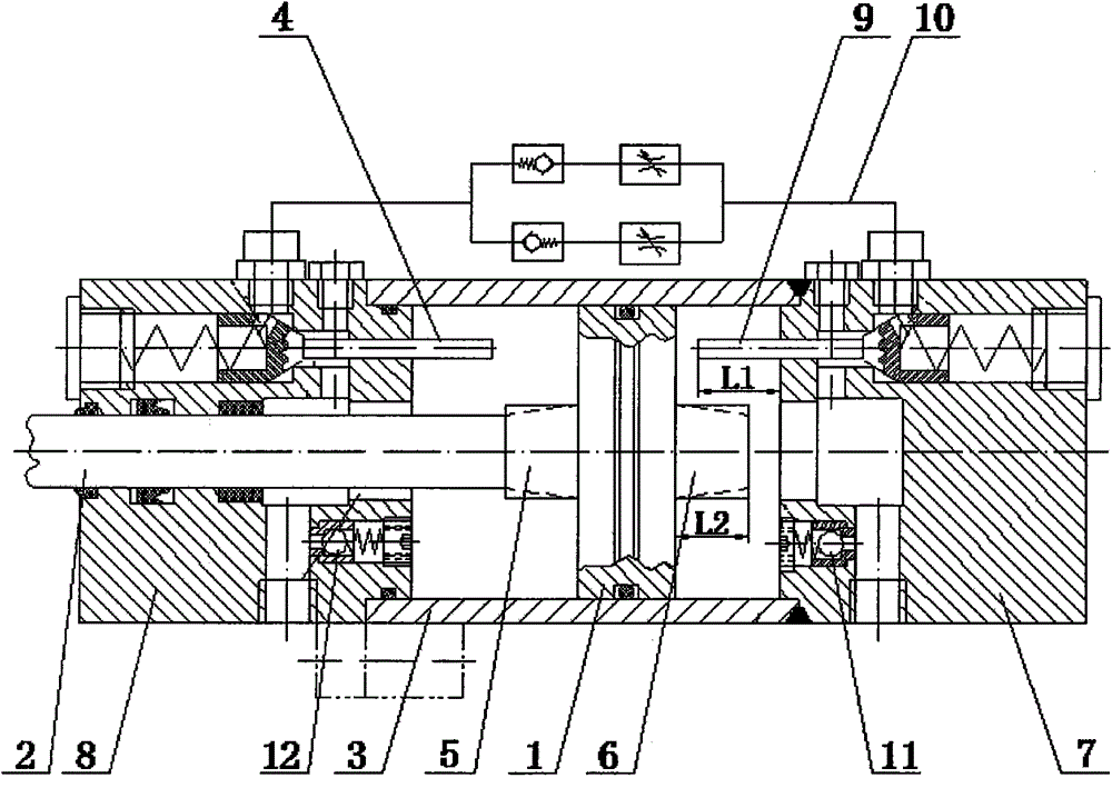
[0029] An oil cylinder device for cushioning after unloading of the present invention comprises: a cylinder bottom 7, a cylinder barrel 3, a cylinder cover 8, a buffer piston and two check valve pistons with the same structure,

[0030] The connection between the piston head 1 and the piston rod 2 of the buffer piston is processed with a cylindrical buffer plunger A5 with an outer diameter larger than that of the piston rod, and the front end center of the piston head 1 extends forward from the cylindrical buffer plunger B6. The side walls of the buffer plunger at both ends of the piston head 1 are processed with oil inlet grooves gradually expanding from the piston head 1 to both sides.

[0031] The end of one end of the piston head of the check valve piston is processed with a spring installation groove. There are connected oil inlet holes;

[0032] The inner diameter of the cylinder barrel 3 matches the outer diameter of the piston head 1 in the buffer piston;

[0033] Th...


PUM


Abstract

The invention relates to a buffer-after-unloading oil cylinder device, belonging to the technical field of hydraulic control. The buffer-after-unloading oil cylinder device comprises a cylinder bottom, a cylinder tube, a cylinder lid, a buffer piston and two one-way valve pistons with the same structure. By designing an unloading circuit and matching with the slit buffer structure for comprehensive use, the buffer cylinder implements the function of buffer after unloading, and has the effects of reducing the peak value of the buffering power, shortening the buffer stroke and smoothing the buffer.

Description

technical field [0001] The invention relates to an oil cylinder device for cushioning after unloading, and belongs to the technical field of hydraulic control. Background technique [0002] With the development of construction machinery hydraulic technology and market, the movement speed of construction machinery hydraulic cylinder piston is required to be higher and higher. In order to prevent the piston from hitting the cylinder head or cylinder bottom at both ends of the stroke, generating noise, affecting the working accuracy and even damaging the parts, often Buffer devices are installed at both ends of the hydraulic cylinder. [0003] There are basically two buffer structures for traditional hydraulic cylinders: one is the external control of the hydraulic cylinder, that is, a throttle valve or other forms of flow control devices are installed on the external control circuit of the hydraulic cylinder for throttling and buffering control; the other is It is the interna...

Claims


Application Information

Patent Timeline
Patent Type & Authority Patents(China)
IPC IPC(8): F15B15/14F15B15/22
Inventor 韩美香郭太清李宜丁李忠九祁小晶
Owner SHANXI NORTH MACHINE BUILDING
Why Eureka
Try Eureka