
A vacuum three-position switch with quick grounding knife

A grounding knife, three-position technology, used in electrical switches, high-voltage/high-current switches, high-voltage air circuit breakers, etc., can solve the problems of high requirements for guide sleeves, potential safety hazards, complex structures, etc., and achieve low cost and structure. Simple, small size effect

Inactive Publication Date: 2016-02-10
沈阳华德海泰电子有限公司
View PDF6 Cites 0 Cited by
  • Summary
  • Abstract
  • Description
  • Claims
  • Application Information

AI Technical Summary

Problems solved by technology

"Therefore, although the invention has a fast grounding switch, the fast grounding switch is arranged horizontally, which is affected by gravity, and has higher requirements on the guide sleeve, and there are many openings on the tank body, and the probability of air leakage is relatively high, posing safety hazards. The moving contact of the isolating switch also needs to be opened and closed through two connecting plates and a crank arm, which also has the problems of complex structure, large volume and high cost

Method used


Image

  • A vacuum three-position switch with quick grounding knife
  • A vacuum three-position switch with quick grounding knife
  • A vacuum three-position switch with quick grounding knife

Examples


Embodiment Construction

[0038] Specific embodiments of the present invention are provided below in conjunction with the accompanying drawings.

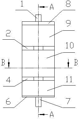
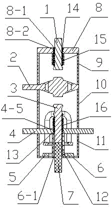
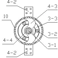
[0039] As shown in the drawings, the present invention includes an upper insulating cylinder 9, a middle insulating cylinder 10 and a lower insulating cylinder 11. An upper cover plate 8 is welded on the top of the upper insulating cylinder 9, and the center of the upper cover plate 8 is processed with a center of the upper cover plate. The hole 8-1 is used as the outlet of the fast grounding knife conductor 1; the fast grounding knife conductor 1 is installed in the center hole 8-1 of the upper cover plate, and the center hole of the upper cover plate is processed on the center hole 8-1 of the upper cover plate Groove 8-2, the second Basel spring 14 is installed at the groove 8-2 in the center hole of the upper cover plate, and the isolated conductor 2 is welded between the upper insulating cylinder 9 and the middle insulating cylinder 10, and the middle ins...


PUM


Abstract

A vacuum three-position switch with a rapid earth switch overcomes the defects that in the prior art, an existing switch is complex in structure, large in size, high in cost, incomplete in function and poor in safety. The vacuum three-position switch with the rapid earth switch is characterized in that a rapid earth switch electric conductor is arranged in a central hole of an upper cover plate which is welded to the top end of an upper insulating cylinder, an isolation electric conductor is welded between the upper insulating cylinder and a middle insulating cylinder, an outgoing line electric conductor is welded to the middle insulating cylinder and a lower insulating cylinder through an annular connecting body of the outgoing line electric conductor, a movable electric conductor which is fixedly connected with an insulating pull rod is arranged in a hollow guide sleeve welded to the upper side of a central hole of a lower cover plate, and the axis of the rapid earth switch electric conductor, the axis of the insulating electric conductor, the axis of the movable electric conductor, the axis of the outgoing line electric conductor, the axis of an earth electric conductor, the axis of the upper insulating cylinder, the axis of the middle insulating cylinder and the axis of the lower insulating cylinder are in the same line. The vacuum three-position switch with the rapid earth switch has the advantages that due to the fact that the movable electric conductor moves perpendicularly, a crank is omitted, the concentricity of the movable electric conductor, the insulating electric conductor and the earth electric conductor can be easily guaranteed, the machining difficulty of the guide sleeve is lowered, and the vacuum three-position switch with the rapid earth switch is simple in structure, small in size, low in cost, complete in function and high in safety.

Description

technical field [0001] The invention belongs to the technical field of high-voltage electrical appliances, in particular to a vacuum three-position switch with a quick grounding knife. Background technique [0002] The three-position switch is an important component of switchgear on high-voltage power transmission and distribution, and plays a very important role in the entire power transmission and distribution system. In the prior art, the three-position switch generally uses the moving conductor to be placed obliquely, and the concentricity requirements of the moving conductor, the isolation conductor and the grounding conductor are relatively high. Due to the influence of gravity, it is difficult to ensure that the moving conductor, the isolation conductor and the grounding conductor are electrically conductive. The concentricity of the body causes the Basel spring to scratch the bottom of the conductor, causing the silver-plated layer of the conductor to fall off. It is...

Claims


Application Information

Patent Timeline
Patent Type & Authority Patents(China)
IPC IPC(8): H01H33/66
Inventor 张交锁张军侯亚平王政金玉华国世峥
Owner 沈阳华德海泰电子有限公司
Learn More